The transition from the 2022 to the 2025 edition of NFPA 13 introduces a wide range of updates that impact how sprinkler systems are designed, installed, and reviewed. While many revisions are subtle, others represent meaningful shifts in technical requirements, terminology, and overall design approach.
This page highlights the most important differences between the two editions, focusing on changes that affect real-world application. The goal is to give designers, contractors, and authorities having jurisdiction a clear understanding of what has changed, why it matters, and how it may influence current and future projects.
Synthesis of Key Changes
Purpose of this Synthesis
This document provides a chapter-by-chapter comparison of the 2022 and 2025 editions of NFPA 13, Standard for the Installation of Sprinkler Systems. The 2025 edition introduces a substantial number of changes — some are minor terminology updates, while others reflect significant shifts in design philosophy, performance requirements, and the structural organization of the standard itself.
The synthesis below summarizes the most impactful changes a designer, installer, plan reviewer, or AHJ should be aware of when transitioning from the 2022 edition to the 2025 edition. It is organized thematically rather than by chapter so that the practical implications of the update can be quickly understood. Detailed clause-level changes follow this synthesis in the body of the document.
High-Level Themes of the 2025 Revision
Five overarching themes characterize the 2025 update. Recognizing these themes makes the individual changes easier to interpret because most clause edits trace back to one of them.
- A pivot from "fire-stopping" toward "blocking." Throughout the standard, the term and concept of fire-stopping at concealed-space penetrations has been replaced with the new defined term "Blocking" (3.3.22). Blocking is no longer required to be of fire-resistance-rated material — it must simply be noncombustible (when structural members are noncombustible) and remain in place long enough to interrupt the horizontal channeling of heat so ceiling sprinklers can operate in time. This change, driven by FM Global large-scale testing, decouples NFPA 13 from the building code's fire-resistance requirements and refocuses the provision on its actual fire-protection purpose.
- Formal recognition of "Supplemental Sprinklers." The 2025 edition introduces "Supplemental Sprinkler" as a defined term (3.3.223.3.6) and reorganizes the obstruction-protection framework around it (Section 9.5.5.3). Supplemental sprinklers are sprinklers installed below an obstruction to ensure adequate coverage. The new framework specifies their thermal sensitivity, K-factor relationship to the ceiling sprinklers, water-shielding requirements, and design approach (new Section 19.5). This is one of the most substantive technical reorganizations in the 2025 edition and affects many chapters that previously had their own obstruction sub-rules.
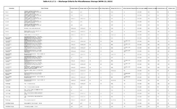
- Consolidation and tabulation of design criteria. Section 4.3.1.7 has been reorganized so that protection criteria for miscellaneous and low-piled storage are now consolidated into two tables (Tables 4.3.1.7.1 and 4.3.1.7.4). These tables capture storage height, maximum ceiling height, design criteria reference, in-rack sprinkler requirements, hose demand, and duration in a single place. The same consolidation philosophy appears in Chapter 8 (dry, preaction, and deluge sections were reorganized) and Chapter 16 (drainage rules for dry and preaction systems collapsed into one).
- Tighter performance requirements at high ceilings (>30 ft). Several new clauses restrict sprinkler selection and increase design density/area where ceiling heights exceed 30 ft (9.1 m) in Ordinary Hazard Group 2 and higher occupancies (10.2.5, 9.4.5, and 19.2.3.2.5.2). Standard-response standard-coverage sprinklers and small-K-factor sprinklers (<K-11.2) are no longer permitted in OH2 with ceilings over 30 ft. Required design densities for OH2 above 30 ft step up to 0.37 gpm/ft² (≤40 ft) and 0.45 gpm/ft² (>40 ft). Extra Hazard 1 and 2 design densities have likewise been increased to 0.45 gpm/ft² above 30 ft. These changes are backed by full-scale fire test data referenced in Annex C.
- Codification of new system types and corrosion-control methods. The 2025 edition formally recognizes Vacuum Dry Pipe and Vacuum Preaction systems (new Section 8.11), Vapor Corrosion Inhibitor (VCI) systems (new Section 8.2.11), and a broader set of corrosion-mitigation options including listed nitrogen generators, 98% pure nitrogen, and listed VCI delivery systems (16.4.2.4 and 16.4.2.5). The "automatic breach control valve" is now defined in 3.3.243.2 — and explicitly prohibited on sprinkler systems by new Section 7.6.3.
Most Impactful Changes by Practitioner Role
For Designers
Owner's Certificate is now the "Basis of Design" (Section 4.2). New required information includes a separate storage layout, an explicit determination and confirmation of water supply (with annex guidance on adjusting raw flow-test data for daily and seasonal fluctuations), and any special knowledge of airborne chemicals that might contact system components.
Density/area curves are no longer permitted for new design (19.2.3.1.1). Only single-point density/area from Table 19.2.3.1.1, room design method, and special design areas remain. Density/area curves were retained in 2022 for evaluation or modification of existing systems; in 2025 they are deleted entirely.
OH2 ceilings over 30 ft trigger multiple new constraints (10.2.5, 9.4.5, 19.2.3.2.5.2). Standard-response sprinklers are not permitted; sprinklers with K-factor <K-11.2 are not permitted; design density steps up to 0.37 or 0.45 gpm/ft² depending on ceiling height; design areas increase by 30%.
New design rules for sloped ceilings exceeding 2 in 12 (Sections 9.5.4.3 and 19.2.3.2.4). For storage occupancies under sloped ceilings >2 in 12, deflectors must be installed parallel to the floor (not parallel to the ceiling). For nonstorage spray-sprinkler designs under slopes >2 in 12, designers must either install a horizontal false ceiling, accept a 30% design-area increase, or comply with a new sprinkler-in-channel layout option (≤4 in 12 slopes only).
Pipe-schedule design is more restricted (19.2.2.3). The 2025 edition removes the allowance for pipe-schedule additions/modifications to existing pipe-schedule systems and existing extra hazard pipe-schedule systems. Pipe schedule remains permitted only for new systems ≤5,000 ft² (and >5,000 ft² where 50 psi is available at the highest sprinkler).
ESFR slope limit increased from 2 in 12 to 4 in 12 (14.2.3). This is a notable expansion of where ESFR may be applied.
A new "supplemental sprinkler" design path (Section 19.5). Where supplemental sprinklers are required by 28.2.4.7.4.3 to be included in hydraulic calculations, the design approach may be based on the hazard located directly below the obstruction rather than the ceiling hazard.
For Installers and Contractors
Minimum nominal pipe sizes are now codified (Section 16.3). New explicit minimums: 1 in. for black or galvanized steel pipe (welded, roll-grooved, or threaded); ¾ in. for nonmetallic pipe, copper tube, brass pipe, and stainless steel pipe.
Flexible sprinkler hose fitting length is now limited (16.8.8). 12 ft (3.7 m) maximum above rigid ceilings; 6 ft (1.8 m) maximum above acoustical tile and lay-in panel ceilings.
Mechanical-damage shield plates must extend 2 in. along the structural member (16.4.4). A new explicit requirement that supplements the existing thickness rule for nonmetal pipe routed near edges of studs/joists.
Spare-sprinkler stock requirements expanded (16.2.7). The required list now includes orientation, manufacturer's sprinkler wrench model number for each sprinkler type, and quantity installed in the property (in addition to the 2022 information).
New Documentation Cabinet requirement (16.11.1.3). A documentation cabinet — sized to contain all necessary documentation in electronic or hardcopy format — must be installed at an approved location and must contain at minimum the final record-of-completion documents, final shop drawings, and as-builts. Section 16.17 ("Reserved" in 2022) now requires that copies of all required signage information also be kept in this cabinet.
Pressure gauges: maximum limit reduced from 2× to 1.5× working pressure (16.13.3). A meaningful change for ordering and stocking gauges.
Blocking replaces firestopping at floor pipe penetrations (9.2.1.16.2). The requirement for materials equivalent to floor construction is deleted in favor of simple blocking.
For Plan Reviewers and AHJs
New Annex A.1.5 explicitly discourages "mixing provisions" between editions. It supports adopting a newer edition in its entirety. Reviewers should be alert to projects that attempt to combine 2022 and 2025 provisions selectively.
Light hazard wet-pipe systems may now exceed 52,000 ft². Section 4.4.1(2) permits up to 78,000 ft² (7,250 m²) where flow and supervisory alarms are transmitted to a supervising station per NFPA 72. Annex commentary cautions that the larger area increases the operational and economic impact of impairments.
Elevators are extensively reorganized (9.2.14 and 9.3.6). New explicit allowances permit omission of sprinklers in elevator pits and at the top of hoistways under specified conditions. Top-of-hoistway sprinklers are now required only where combustible suspension means do not pass UL 2556 FT-1 vertical-burn criteria. Where sprinklers are provided in machine rooms, machinery spaces, control rooms, control spaces, or hoistways, they must be standard-response spray sprinklers.
Pre-action and deluge detection requirements are tightened (Section 8.10). Section 8.10 has been substantially restructured. New explicit requirements include: pilot-line detectors installed upright on dry pilot lines (8.10.3.9); dry pilot lines pitched at 1/2 in. per 10 ft (8.10.3.10); and an independent air supply for dry pilot lines so pilot pressure can be maintained separately from system pressure (8.10.3.11). Actuator supervision (8.3.1.3) now covers both removal and disabling of an electric actuator.
Automatic breach control valves are prohibited (7.6.3). These valves close on detection of abnormal flow, which conflicts with the goals of fire control and suppression. The annex notes that closed valves remain the single largest cause of sprinkler-system failure, and that fire-department-connection flow can exceed hydraulic-calculation flow during a fire.
Freeze-protection threshold changes (16.4.1.1.1). "Lowest mean temperature for one day" is replaced by "average annual extreme minimum temperature" — a different and generally more conservative reference value that should be confirmed during plan review.
Notable New Content in 2025
Section 8.11 — Vacuum Systems. Vacuum dry pipe and vacuum preaction systems are recognized as system types. They inherit the rules of Sections 8.2 and 8.3 respectively, with listing requirements for the vacuum equipment and for sprinklers used under vacuum, and reliance on manufacturer's instructions for relief-valve settings.
Section 8.2.11 — Vapor Corrosion Inhibitor systems. VCIs are recognized as a corrosion-control option for dry systems. Equipment must be listed, permanently installed per manufacturer's instructions, maintained per Chapter 32, and provided with a means of verifying vapor concentration.
New defined terms (Chapter 3). Alcove (3.3.5), Area of Discharge (3.3.8), Blocking (3.3.22), Hose Station (3.3.111), Non-Flat Obstruction (3.3.143), Non-Solid Obstruction (3.3.144), Panel Construction (3.3.164), Qualified Personnel (3.3.183), Supplemental Sprinkler (3.3.223.3.6), Vacuum Dry System and Vacuum Preaction System (3.3.224.10), Automatic Breach Control Valve (3.3.243.2), and Vapor Corrosion Inhibitor (3.3.244).
New low-piled storage table (Table 4.3.1.7.4). A standalone discharge-criteria table for low-piled storage that mirrors the structure of the miscellaneous-storage table.
New Section 7.10 — Air Supply. Where an air compressor is dedicated to a sprinkler system, it must be listed for fire protection.
New Section 9.3.16.2 — Skylight protection. Where a skylight does not meet 9.3.16.1, it may be protected as a ceiling pocket per Chapters 10 through 14.
Terminology and Editorial Changes Worth Noting
"Air pressure" → "pneumatic pressure" throughout dry-system provisions, with "air includes nitrogen and other approved gases" handled centrally in Section 4.7.
"Dry Pipe Systems" (Section 8.2 title) → "Dry Systems."
"Owner's Certificate" (Section 4.2 title) → "Basis of Design for the Owner's Certificate."
"Deflector horizontal" → "deflector parallel to the floor" (Sections 10.2.7.2.2 and 10.2.7.2.3).
"Tight construction" (floor over space) → "constructed in such a manner as to prevent the passage of debris into the space below" (9.2.2(3)).
"Experienced personnel" → "trained personnel" in 1.2.2, paired with the new definition of "Qualified Personnel" in 3.3.183.
NFPA 1963 → NFPA 1960 (Section 16.12.3.1 and Chapter 2). The fire-hose-connection thread reference now points to the broader-scope NFPA 1960.
"Single-outlet" FDC → "single-inlet" FDC (16.12.3.1.3) — corrects long-standing terminology.
How to Read the Detailed Comparison That Follows
The remainder of this document is organized in NFPA 13 chapter and section order. For each section that changed between 2022 and 2025, the entry shows the relevant 2022 text, the 2025 text, and where applicable the annex commentary, enhanced-content notes, and the underlying technical basis (such as a referenced FM Global or Fire Protection Research Foundation test program). New sections are flagged "(New in 2025)"; deleted clauses are flagged "(Deleted in 2025)"; and renumbered clauses are tagged with their 2022 origin.
Designers should pay particular attention to Chapters 4, 9, 10, 13, 14, 19, and 25, which contain the most significant technical-design changes. Installers and inspectors should focus on Chapters 7, 8, 16, and 17. Plan reviewers and AHJs will want to review the entirety of Chapter 9 and Section 4.3 closely, as well as the new Section 8.11 (Vacuum Systems) and the reorganized obstruction framework in Section 9.5.5.3.
This synthesis is intended to orient the reader; it is not a substitute for reading the underlying clause text or the official NFPA 13 (2025) standard. Where a clause-level decision turns on subtle wording, the detailed comparison in the chapters that follow should be consulted, and the official standard should be the controlling reference.
Table of Contents
- Chapter 1 – Administration
- Chapter 2 – Referenced Publications
- Chapter 3 – Definitions
- Chapter 4 – General Requirements
- Chapter 5 – Water Supplies
- Chapter 6 – Installation Underground Piping
- Chapter 7 – Requirements for System Components and Hardware
- Chapter 8 – System Types and Requirements
- Chapter 9 – Sprinkler Location Requirements
- Chapter 10 – Standard Pendent, Upright, and Sidewall Spray Sprinklers
- Chapter 11 – Extended Coverage Upright, Pendent, and Sidewall Spray Sprinklers
- Chapter 12 – Residential Sprinklers
- Chapter 13 – CMSA Sprinklers
- Chapter 14 – ESFR Sprinklers
- Chapter 15 – Special Sprinklers
- Chapter 16 – Installation of Piping, Valves, and Appurtenances
- Chapter 17 – Installation of Piping, Valves, and Appurtenances
- Chapter 18 – Seismic Protection
- Chapter 19 – Design Approaches
- Chapter 20 – General Requirements for Storage
- Chapter 21 – High-Piled Storage Using CMDA Sprinklers
- Chapter 22 – CMSA Requirements for Storage Applications
- Chapter 23 – ESFR Requirements for Storage Applications
- Chapter 24 – Alternative Sprinkler System Designs
- Chapter 25 – Rack Storage Using In-Rack Sprinklers
- Chapter 26 – Special Designs of Storage Protection
- Chapter 27 – Special Occupancy Requirements
- Chapter 28 – Plans and Calculations
- Chapter 29 – Systems Acceptance
- Chapter 30 – Existing System Modifications
- Chapter 31 – Marine Systems
- Chapter 32 – System Inspection, Testing, and Maintenance
Chapter 1 – Administration
1.2 Purpose
1.2.2 — Qualified Personnel
- 2022: “Sprinkler systems and private fire service mains are specialized fire protection systems and shall require design and installation by knowledgeable and experienced personnel.”
- 2025: “Sprinkler systems and private fire service mains are specialized fire protection systems and shall require design and installation by knowledgeable and trained personnel.”
1.5 Equivalency
- 2025 adds Annex A.1.5 clarifying edition adoption lag and discouraging “mixing provisions,” supporting use of a newer edition in its entirety when allowed.
- 2025 changes “Nothing in this standard is intended to prevent the use of systems, methods, or devices of equivalent or superior quality” to “Nothing in this standard shall prevent the use of systems, methods, or devices of equivalent or superior quality”.
Chapter 2 – Referenced Publications
2.2 NFPA Publications
NFPA 11: 2021 → 2024
NFPA 14: 2019 → 2024
NFPA 20: 2022 → 2025
NFPA 22: 2018 → 2023
NFPA 25: 2020 → 2023
NFPA 30: 2021 → 2024
NFPA 30B: 2019 → 2023
NFPA 33/34: 2021 → 2024
NFPA 36: 2021 → 2025
NFPA 37: 2021 → 2024
NFPA 40: 2019 → 2025
NFPA 45: 2019 → 2024
NFPA 51: 2018 → 2023
NFPA 51B: 2019 → 2024
NFPA 55: 2020 → 2023
NFPA 59: 2021 → 2024
NFPA 59A: 2019 → 2023
NFPA 70 (NEC): 2020 → 2023
NFPA 72: 2022 → 2025
NFPA 75/76: 2020 → 2024
NFPA 82: 2019 → 2024
NFPA 86: 2019 → 2023
NFPA 96: 2021 → 2024
NFPA 99: 2021 → 2024
NFPA 101: 2021 → 2024
NFPA 120/122/130: 2020 → 2023
NFPA 140: 2018 → 2024
NFPA 150: 2022 → 2025
NFPA 170: 2021 → 2024
NFPA 259: 2018 → 2023
NFPA 409/415/423: 2016 → 2022
NFPA 701: 2019 → 2023
NFPA 703: 2021 → 2024
NFPA 750: 2019 → 2023
NFPA 780: 2020 → 2023
NFPA 909: 2017 → 2021
NFPA 318: 2021 → 2025
NFPA 400: 2022 → 2025
Items that remain unchanged:
NFPA 32: stays 2021
NFPA 91: stays 2020
NFPA 214: stays 2021
NFPA 307: stays 2021
NFPA 804/805: stay 2020
Additions / substitutions
NFPA 915 added (2025): Standard for Remote Inspections and Tests, 2024 Edition.
NFPA 1963 replaced by NFPA 1960 (2025):
- 2022 list: NFPA 1963, Standard for Fire Hose Connections, 2019 Edition.
- 2025 list: NFPA 1960, broader-scope title, 2024 Edition (hose connections plus additional equipment categories, per the title as printed).
2.3 Other Publications
2.3.1 ACI Publications
- ACI 318: 2014 + errata history → 2019, reapproved 2022
2.3.3 ASME Publications
- Boiler and Pressure Vessel Code Section IX: 2019 → 2021
- A17.1 elevator/escalator standard: 2019/CSA B44-16 → 2022 (A17.1/CSA B44)
- B1.20.1: 2013 → 2018
- B16 series:
- B16.1: 2015 → 2020
- B16.3: 2016 → 2021
- B16.4: 2016 → 2021
- B16.5: 2017 → 2020
- B16.11: 2016(+errata) → 2021
- B16.18: 2018 → 2021
- B16.22: 2018 → 2021
2.3.4 ASTM Publications
- A53: 2018 → 2022
- A135: 2009 (reapproved 2014) → 2021
- A234: 2019 → 2023
- A312: 2019 → 2022
- A403: 2020 → 2022
- A795: 2020 → 2021
- B32: 2008 (reapproved 2014) → 2020
- B88: 2020 → 2022
- C635: 2017 → 2022
- E84: 2020 → 2021
- E119: 2020 → 2022
- E136: 2019a → 2022
- E2652: 2018 → 2022
- E2965: 2017 → 2022
- F437: 2015 → 2021
- F438: 2017 → 2023
- F442: 2019 → 2023
2.3.5 AWS Publications
- AWS B2.1 updated: 2014 → 2021
- AWS A5.8 remains 2019.
2.3.6 AWAA Publications
- C104: 2016 → 2023
- C110: 2012 → 2021
- C115: 2011 → 2020
- C150: 2014 → 2021
- C300/C302: 2016 → 2022
- C602: 2017 → 2023
- C900: 2016 → 2022
- C906: 2015 (4–63 in) → 2021 (4–65 in) (note also dimensional range changed in title line)
- C909: 2016 (4 in and larger) → 2022 (4–24 in) and expanded application wording (water/wastewater/reclaimed water)
- M9 errata year: 2013 → 2014
- M23: 2002 → 2020
- M55: 2006 → 2020
2.3.9 UL Publications
- UL 263: revised 2018 → revised 2022
- UL 2556: 2015 → revised 2021
Other Publications
Merriam-Webster’s Collegiate Dictionary: 11th ed., 2003 → 11th ed., 2020
2.4 References for Extracts in Mandatory Sections
2022 list
- NFPA 1: 2021 → 2024
- NFPA 14 (2024) (new addition)
- NFPA 20: 2022 → 2025
- NFPA 24: 2022 → 2025
- NFPA 25: 2020 → Removed
- NFPA 5000: 2021 → 2024
Chapter 3 – Definitions
3.3 General Definitions
3.3.5 Alcove (New in 2025)
2025:“An area in a compartment or corridor that is set back from the rest of the wall it is located along.”
Annex: While most alcoves requiring sprinkler protection are enclosed on three sides, some alcoves are designed as an architectural feature with curved walls or other configurations. The area is incidental to the space it is adjacent to, is typically enclosed on three sides, and might contain a lower ceiling and/or an elevated floor. (AUT-SSI).
3.3.8 Area of Discharge (New in 2025)
2025: “The floor area covered by a sprinkler that takes into account any walls or obstructions whose summation determines the remote area. (See Figure A.28.2.4.2.1.)”
3.3.22 Blocking (New in 2025)
2025: “A means by which the horizontal spread of flame or heat during a fire event is stopped by the installation of materials that will stay in place before and during sprinkler operation to limit the channeling of heat between structural members. (AUT-SSD).”
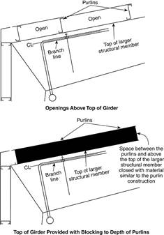
Annex: “Blocking is required in several instances within this standard to restrict the horizontal flow of heat within channels created by obstructed construction, which is referred to as channeling. The blocking helps reduce the channeling effect created by obstructed construction so that the heat from a fire can fill a specified channel volume before eventually flowing horizontally under the structural members and activating ceiling sprinklers in a timely fashion. See for an example of blocking a purlin at the intersection of a girder. The material utilized for blocking does not have to have a fire resistive rating, rather it only requires noncombustible materials for the blocking when the structural elements are noncombustible. While it is ideal to have blocking that is tight to the ceiling, the intent of this section is to not require the small gaps created by a corrugated roof decking to be filled. (AUT-SSD).”
Enhanced Content note: says it was added due to FM Global large-scale fire tests and explains why it matters (channeling, premature/delayed operation).
3.3.69 Dwelling Unit (for sprinkler system installations).
2025: Annex “Common spaces such as a lounges, group cooking facilities, and group bathrooms that are for use by the occupants of the building should be considered a part of the dwelling unit. (AUT-SSI)”
3.3.111 Hose Station (New in 2025)
2025: “A combination of a hose rack or reel, hose nozzle, hose, and hose connection. [14, 2024] (AUT-SSI)”
3.3.143 Non-Flat Obstruction (New in 2025)
2025: “An obstruction where the underside of the obstruction is not in the same plane and not capable of collecting heat. (AUT-SSI)”
- Annex: “An example of a non-flat obstruction would be a round duct or pipe. (AUT-SSI)”
3.3.144 Non-Solid Obstruction (New in 2025)
2025: “An obstruction that consists of openings that constitute at least 30 percent of the footprint of the obstruction. (AUT-SSI)”
- Annex: “Examples of a non-solid obstruction would include (1) a cable tray where the number of cables provided in the tray allow for openings that constitute 30 percent or more of the tray’s footprint, or (2) a grouped obstruction where the open space between the objects within the footprint of the grouped obstruction is 30 percent or more. (AUT-SSI)”
3.3.164 Panel Construction (New in 2025)
2025: “Ceiling panels formed by members capable of trapping heat to aid the operation of sprinklers and limited to a maximum of 300 ft2 (28 m2) in area. See . (AUT-SSI)”
3.3.183 Qualified Personnel (New in 2025)
2025: “Competent and capable individual(s) having met the requirements and training for a given field acceptable to the AHJ. [25, 2023] (AUT-SSI)”
3.3.223 Sprinkler Definitions
3.3.223.3.6 Supplemental Sprinkler (New in 2025)
2025: “A sprinkler that is installed below an obstruction. (AUT-SSI)”
Sprinkler System
General Definition:2022: “…that includes a water supply source, a control valve, a waterflow alarm, and a drain.”
2025: “…that includes a water supply source, a control valve, a waterflow alarm (where required), and a drain.”
3.3.224.4 Dry Pipe Sprinkler System.
2022:“…attached to a piping system containing air or nitrogen under pressure…”
2025: “…attached to a piping system containing air, nitrogen, or other approved gas under pressure…”
3.3.224.10 Vacuum Dry System. (New in 2025)
2025: “A sprinkler system employing automatic sprinklers that are attached to a piping system containing air under negative gauge pressure, the release of which (as from the opening of a sprinkler) permits the air pressure detection to open the water flow valve, and the water then flows into the piping system and out the opened sprinklers. (AUT-SSI)”
3.3.224.10 Vacuum Preaction System. (New in 2025)
2025: “A sprinkler system employing automatic sprinklers that are attached to a piping system containing air under negative gauge pressure, with a supplemental detection system installed in the same areas as the sprinklers. (AUT-SSI)”
3.3.243 Valve
3.3.243.2 Automatic Breach Control Valve.
2025: “A hydraulic sensing device that detects abnormal water flow conditions and automatically isolates portions of a piping system when a catastrophic downstream breach or line break occurs. (AUT-SSI)”
- Annex: “Also known as a breach valve and an automatic breach containment valve. (AUT-SSI)”
3.3.243.5.3 Deluge Valve.
2025: “A water control valve, used for deluge and preaction systems, that is held in the closed position by hydraulic pressure operating on a series of mechanical devices such as levers, pistons, springs, diaphragms, and latches, wherein the loss of hydraulic pressure due to automatic or manual operation of a releasing device or devices results in operation of the deluge valve. (AUT-SSI)”
3.3.244* Vapor Corrosion Inhibitor (VCI).
2025: A chemical compound (substance) that emits rust-inhibiting vapor to protect ferrous and nonferrous metals against corrosion in air-filled dry pipe or preaction sprinkler systems. (AUT-SSI)
- Annex: VCIs are also referred to as vapor phase corrosion inhibitors, volatile corrosion inhibitors, and vapor phase inhibitors (VPI). All of these terms relate to a specific class of corrosion inhibitors. The inhibitor forms a thin protective layer through adsorption separating the pipe from the air or water and provides protection against corrosion. Other classifications include passivating (anodic), cathodic, organic, and precipitation inhibitors. VCIs are appropriate for atmospheric or gaseous corrosion. This is corrosion happening in the air-filled portion of the sprinkler system containing water vapor. Corrosion will occur when the relative humidity is greater than 60 percent. VCIs can also provide protection in partially aqueous environments (partially water-filled pipes) and aqueous environments (water-filled pipes). VCIs can inhibit anodic reactors, cathodic reactions, or both. VCIs protecting against both anodic and cathodic reactions provide the best level of protection for applications in sprinkler systems. (AUT-SSI)
Chapter 4 – General Requirements
4.2 Basis of Design for the Owner’s Certificate
2022 Title: 4.2 Owner’s Certificate.
2025 Title: 4.2 Basis of Design for the Owner’s Certificate.
Required Information:
2022:
- Intended use of the building, including the materials within the building and the maximum height of any storage
- A preliminary plan of the building or structure along with the design concepts necessary to perform the layout and detail
- Water supply information as identified in 5.2.2
- Any special knowledge of the water supply, including known environmental conditions that might be responsible for corrosion, including MIC
- Whether seismic protection is required and the applicable design spectral response acceleration at short periods, SDS
2025:
- Intended use of the building, including the materials within the building and the maximum height and arrangement of any storage configuration
- New: Storage layout, including the maximum height, storage commodity, and arrangement of any storage configuration, where applicable
- A preliminary plan of the building or structure along with the design concepts necessary to perform the layout and detail
-
New: Determination and confirmation of the water supply including any necessary adjustments
- Annex: “Where a waterflow test was conducted to provide the water supply information, the raw data from the test should be evaluated to determine if an adjustment is appropriate. The evaluation should be based on knowledge of the water supply and engineering judgment, taking into account daily and seasonal fluctuations, not extreme conditions.
- The evaluation can be based on information from the water supply authority, testing, modeling, the fire or building department, or knowledge of the water supply from having worked previously in the jurisdiction. Depending on how much the pressure changes over time at any given location, an adjustment might or might not be appropriate. For mature water supplies (ones where new development in the vicinity is unlikely because available property has been fully developed) with fairly stable water usage, or where the waterflow test was conducted at a time of low pressure already, a very small adjustment or no adjustment at all might be appropriate. For situations where the waterflow test was performed at a time of low demand when it is known that higher demands occur at other times of day or other times of the year, then a larger adjustment would be appropriate.
-
The evaluation to determine whether an adjustment should be made, and the size of such an adjustment if one is needed, should take into account the following variables, which will be applicable to different degrees depending on how and when the test was conducted:
- Maximum daily use of the water supply
- Peak hour demand of the water supply
- Water supply degradation due to planned development
- Time of day the test was conducted
- Time of year the test was conducted
- Elevation of the test location compared to the building where the sprinkler system will be installed
- Elevation of the water supply at the time of the test
- How close the flow generated during the test was to the system demand
- There is no single specific adjustment that can be applied to every water supply that would be appropriate for every sprinkler system. The design professional needs to work in conjunction with the authority having jurisdiction to determine an appropriate adjustment. Where an authority having jurisdiction has already determined a specific buffer between test results and the demand of the sprinkler system, there is no intent to add an additional safety factor or safety margin due to this requirement. Instead, the buffer mandated by the authority having jurisdiction serves the purpose of this adjustment.
- If an adjustment is determined to be appropriate, it should be applied to the waterflow test data prior to comparison with the sprinkler system demand.
- Where the water supply information was obtained from another approved method instead of a waterflow test, that method should take into account daily and seasonal fluctuations, not extreme conditions. It is important to note that adjustments are not intended to handle extreme or catastrophic conditions such as water main breaks. Such extreme conditions are accounted for in NFPA 25 with impairment procedures to follow when systems are out of service.
- In the absence of information from the design professional and the authority having jurisdiction, it would be appropriate to make an adjustment to the raw data from a flow test by either obtaining information from the water utility or using an arbitrary adjustment. The value to use for an arbitrary adjustment should be determined through a conversation with the authority having jurisdiction.”
- Any special knowledge of the water supply, including known environmental conditions that might be responsible for corrosion, including MIC
- Whether seismic protection is required and the design spectral response acceleration at short periods, SDS
- New: Any special knowledge of the general environment … including airborne chemicals or chemical solutions that might contact system components
4.3 Classification of Hazard
4.3.1.7 Protection Criteria for Miscellaneous and Low-Piled Storage.
- In the 2025 edition, Section 4.3.1.7 was reorganized to gather most requirements for miscellaneous and low-piled storage protection into tabular form. The new tables consolidate storage height limits, ceiling height limits, design criteria, hose demand, duration, and in-rack sprinkler requirements, streamlining application and minimizing the need to cross-reference multiple sections.
- 4.3.1.7.1: “The protection criteria for miscellaneous storage protected by ceiling sprinklers only shall be selected from .”
Table 4.3.1.7.1 adds a new column that specifies if In-Rack Sprinklers are Required
- 4.3.1.7.2: “For miscellaneous storage with open frame racks where in-rack sprinklers are required by , one level of in-rack sprinkler protection and ceiling design shall be in accordance with .”
- 4.3.1.7.3 (New in 2025): “For miscellaneous storage having solid shelf racks where in-rack sprinklers are required by Table 4.3.1.7.1, in-rack sprinklers shall be in accordance with Section 25.3 and the ceiling design shall be in accordance with 25.2.1.4. ”
- 4.3.1.7.4 (New in 2025): “The protection criteria for low-piled storage protected by ceiling sprinklers only shall be selected from .”
- Table 4.3.1.7.4 Discharge Criteria for Low-Piled Storage:
| Commodity | Type of Storage | Storage Height (ft / m) | Maximum Ceiling Height (ft / m) | Design from 19.2.3.1.1 | In-Rack Sprinklers Required | Inside Hose (gpm / L/min) | Total Combined Inside and Outside Hose (gpm / L/min) | Duration (minutes) |
|---|---|---|---|---|---|---|---|---|
| Class I | Solid-piled, palletized, bin box, shelf, single-, double-, or multiple-row rack, and back-to-back shelf storage | ≤12 / ≤3.7 | — | OH1 | No, unless solid shelf | 0, 50, 100 / 0, 190, 380 | 250 / 950 | 90 |
| Class II | ≤10 | ≤10 / ≤3.0 | — | OH1 | No, unless solid shelf | 0, 50, 100 / 0, 190, 380 | 250 / 950 | 90 |
| Class II | >10 to ≤12 | >10 / ≤3.7 | — | OH2 | No, unless solid shelf | 0, 50, 100 / 0, 190, 380 | 250 / 950 | 90 |
| Class III | ≤12 | ≤12 / ≤3.7 | — | OH2 | No, unless solid shelf | 0, 50, 100 / 0, 190, 380 | 250 / 950 | 90 |
| Class IV | ≤10 | ≤10 / ≤3.0 | — | OH2 | No, unless solid shelf | 0, 50, 100 / 0, 190, 380 | 250 / 950 | 90 |
| Class IV | Palletized, bin box, shelf, and solid-piled | >10 to ≤12 / ≤3.7 | 32 / 9.8 | OH2 | No, unless solid shelf | 0, 50, 100 / 0, 190, 380 | 250 / 950 | 90 |
| Class IV | Single-, double-, or multiple-row rack, and back-to-back shelf storage | >10 to ≤12 / ≤3.7 | 32 / 9.8 | EH1 | No, unless solid shelf | 0, 50, 100 / 0, 190, 380 | 500 / 1900 | 120 |
| Class IV | Single-, double-, or multiple-row rack | >10 to ≤12 / ≤3.7 | 32 / 9.8 | See 25.2.2 | Yes | 0, 50, 100 / 0, 190, 380 | 250 / 950 | 90 |
| Group A Plastic | Solid-piled, palletized, bin box, shelf, single-, double-, or multiple-row rack, and back-to-back shelf storage | ≤5 / ≤1.5 | — | OH2 | No, unless solid shelf | 0, 50, 100 / 0, 190, 380 | 250 / 950 | 90 |
- 4.3.1.7.5: “For low-piled storage with open frame racks where in-rack sprinklers are required by , one level of in-rack sprinkler protection and ceiling sprinkler design shall be in accordance with .”
- 4.3.1.7.6: “For low-piled storage having solid shelf racks where in-rack sprinklers are required by Table 4.3.1.7.4, in-rack sprinklers shall be in accordance with Section 25.3 and the ceiling design shall be in accordance with 25.2.2.4.”
- 4.3.1.7.7: “Ceiling sprinkler design shall be in accordance with Section 19.2.”
- 4.3.1.7.8: “The maximum design area for miscellaneous and low-piled storage shall not exceed 3000 ft2 (280 m2).”
4.3.2 Light Hazard
Spaces with low quantity and combustibility of contents shall be protected with light hazard occupancy criteria in this standard.
4.3.3 Ordinary Hazard Occupancies
4.3.3.1 Ordinary Hazard (Group 1)
Annex adds: Electric fire pump room
4.3.4 Extra Hazard Occupancies (New)
- This section compiles what used to be 4.3.4 and 4.3.5.
- 4.3.4.2 Extra Hazard (Group 2) (EH2)
- Annex adds: “Diesel fire pump houses and rooms containing pump drivers and fuel tanks”
4.4 System Protection Area Limitations
4.4.1 adds: (2) “Light hazard protected with a wet pipe system and the system water flow and supervisory alarms are transmitted to a supervising station in accordance with NFPA 72 — 78,000 ft2 (7250 m2)”
Annex: “Should the system be impaired, it should be noted that the increased area will result in impairment procedures in accordance with NFPA 25 being applied to the larger area which could have operational and economic impacts on the building.”
4.9 Noncombustible Materials an Limited-Combustible Materials
4.9.2 Limited-Combustible Material.
2022: “A material shall be considered limited-combustible where both conditions (1) and (2), and either 4.9.2.1 or 4.9.2.2 are met…”
2025: “A material shall be considered limited-combustible where one of the following is met:
- NFPA 5000 + 4.9.2.1 or 4.9.2.2
- 4.9.2.3 (ASTM E2965)”
Chapter 5 – Water Supplies
5.1 General
5.1.4 Water
This is the largest substantive change in Chapter 5.
What 2022 had (more prescriptive)
In 2022, 5.1.4 was titled “Water Supply Treatment” and contained:
- 5.1.4.1 Water Supplies and Environmental Conditions (MIC)
Required evaluation for MIC; if found, owner must notify installer and develop a plan using one of several explicit methods (pipe not affected by microbes; treat incoming water with listed bacterial inhibitor; approved monitoring plan; corrosion monitoring station). - 5.1.4.2 Corrosion
Required evaluation for unusual corrosive properties; if found, owner must notify installer and develop a plan using at least one listed method (corrosion-resistant pipe; listed corrosion inhibitor; monitoring; monitoring stations; nitrogen options including 98% pure nitrogen and/or listed nitrogen generator). - 5.1.4.3 Inhibitors
Compatibility requirements (bacterial/corrosion inhibitors with components and with each other).
2025:
5.1.4 is titled “Water” and the enforceable text is significantly condensed:
- 5.1.4.1 still requires evaluation for microbes/MIC conditions (requirement retained).
- 5.1.4.2 still requires evaluation for unusual corrosive properties (requirement retained).
- 5.1.4.3 Inhibitors got a new annex note; however the compatibility requirements remain.
- “Vapor corrosion inhibitors entering a sprinkler system as vapor in the air supply are not part of the water supply. Requirements for air supply are applicable to vapor corrosion inhibitors.
- Vapor corrosion inhibitors are a type of chemical compound that release a vapor that coats the inside of air-filled sprinkler piping and protects it from rust by preventing oxygen from reaching the pipes. These compounds are used in dry and preaction systems only, because the vapor travels through the sprinkler system by air. For more information, see the definition for vapor corrosion inhibitor, which is new to the 2025 edition of NFPA 13.”
What is missing in the 2025 edition:
The explicit “where found, owner shall notify installer and develop a plan using one of the following methods…” lists for MIC and corrosion (including the specific nitrogen prescriptions) are not present in the 2025 edition.
5.2 Types
- 2022: had 5.2.2.1 and 5.2.2.2 (reliable waterworks acceptable; supply determined from flow test or approved method).
- 2025: adds 5.2.2.3:
- “Where a waterflow test was conducted to provide the water supply information, the date, day of the week, and time of day that the test was conducted shall be recorded with the data.”
- Annex: “It is important to note that not all water supplies have a linear relationship of flow to pressure. As flow demand increases, additional water can be provided into the system through multiple pumps, causing complex geometries to the pressure and flow relationship at any given point in the system. Creating multiple flow conditions during a test and getting as close as possible to the sprinkler system demand will help in gaining a complete understanding of the water supply.”
Chapter 6 – Installation Underground Piping
6.1 General
“The requirements of Chapter 6 shall apply to the installation of underground piping used for private fire service mains and any underground piping installed in a sprinkler system.”
- The “Piping” section becomes 6.2 Piping instead of 6.1.
6.2 Piping
- 6.2.1.3.2 (New in 2025): “The requirements of 6.2.1.3 shall not apply to listed stainless steel piping.”
6.4 Connection of Pipe, Fittings, and Appurtena
- 6.4.7 Copper Tube (New in 2025): All joints for the connection of copper tube shall be brazed or joined using pressure fittings as specified in Table 6.3.1.1.
6.5 Protection of Private Fire Service Mains
- 6.5.1.3 Protection from Corrosion
- “Where it is necessary to join metal pipe with pipe of dissimilar metal, the joint shall be insulated against the passage of an electric current using an approved method.”
- (Annex adds): “A stainless steel in-building riser can connect to dissimilar metallic materials such as ductile iron or black steel. The product performance of many installations has not reported any instances of system failures or corrosion.”
6.7 Restraint
6.7.1 Thrust Blocks
- 6.7.1.1.1 (New in 2025): “The anticipated thrust forces shall be based on the test pressure. “
- Annex 6.7.1: Table A.6.7.1(b) Required Horizontal Bearing Block Area (notes) adds “(b) Hydrostatic test pressures should be used when modifying the thrust-force bearing block area by the ratio of the test pressure to 100 psi (6.9 bar).”
- Annex 6.7.1: Table A.6.6.1(c) Horizontal Bearing Strengths, changed the “Bearing Strength, Sb value in kN/m2 to approximated values (whole numbers) of the conversion.
6.10 Backfilling
6.11.2 Acceptance Requirements:
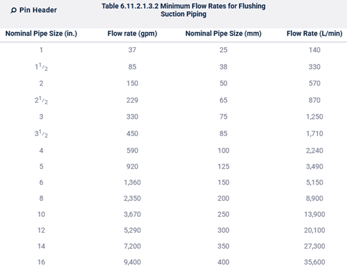
- 6.11.2.1 Flushing of Piping: “When connected to a fire pump, piping shall be flushed at a flow rate not less than indicated in Table 6.11.2.1.3.2 or at the hydraulically calculated water demand rate of the system, whichever is greater.”
-
- “Flushing shall occur prior to hydrostatic test.”
- “Where the maximum flow available from the water supply cannot provide the flow rate provided in Table 6.11.2.1.3.2, the flushing flow rate shall be equal to or greater than 150 percent of rated flow of the connected fire pump.”
- “Where the maximum flow available from the water supply cannot provide a flow of 150 percent of the rated flow of the pump, the flushing flow rate shall be the greater of 100 percent of rated flow of the connected fire pump or the maximum flow demand of the fire protection system.”
- “A reduced flushing flow capacity in accordance with 6.11.2.1.3.2(C) shall constitute an acceptable test, provided that the flow rate is as much as can be safely achieved and it exceeds the fire protection system design flow rate.”
Chapter 7 – Requirements for System Components and Hardware
General
7.1.1 Listing:
Standards Harmonization
- Several UL standards converted to CAN/UL or CAN/UL/ULC designations:
- Sprinklers: UL 199 → CAN/UL/ULC 199
- Fittings: UL 213 → CAN/UL 213
- Aboveground thermoplastic pipe: UL 1821 → CAN/UL 1821
- Underground pipe: UL 1285 → CAN/UL/ULC 1285
- Adds PVCO to underground pipe listing scope (2025)
Category Additions / Reorganization
- New category added: Air Compressors and Vacuum Pumps
- (Standard: UL 1450)
- No category deletions
Terminology / Classification Updates
- FM sprinkler listings updated:
- Suppression Mode ESFR Automatic Sprinklers → Quick Response Storage Sprinklers
- Residential Automatic Sprinklers clarified to “for Fire Protection”
- FM hanger and sway brace category titles updated to reflect:
- broader compatibility with pipe, tubing, conduit
Nomenclature Consistency
- Many UL valve standards updated to explicitly read:
- “for Fire-Protection Service”
- Applied across alarm, dry pipe, deluge, check, gate, butterfly valves
- FM valve listings consolidated:
- FM 1120, 1130 → FM 1120/1130
- FM 1951, 1952, 1953 → FM 1951/1952/1953
Scope Clarifications
- Underground pipe listings now explicitly include:
- Couplings
- Fittings
- Flexible fittings
- FM flexible sprinkler hose listings updated:
- Threaded end fittings now explicitly identified
7.2 Sprinklers
- 7.2.5.1 Corrosion Resitant:
- 7.2.5.1.1 (New in 2025): “Listed corrosion-resistant sprinklers shall be installed in locations where chemicals, moisture, or other corrosive vapors sufficient to cause corrosion of such devices exist.”
- 7.2.5.1.2 (New in 2025): “Unless the requirements of 7.2.5.1.3 are met, corrosion-resistant coatings shall be applied only by the manufacturer of the sprinkler and in accordance with the requirements of 7.2.5.1.3.”
- Annex: “Care should be taken in the handling and installation of wax-coated or similar sprinklers to avoid damaging the coating.”
- 7.2.5.1.3 (New in 2025): “Any damage to the protective coating occurring at the time of installation shall be repaired at once using only the coating of the manufacturer of the sprinkler in the approved manner so that no part of the sprinkler will be exposed after installation has been completed.”
- 7.2.6.2:
- 2022: “Escutcheons used with recessed, flush-type, or concealed sprinklers shall be part of a listed sprinkler assembly.”
- Annex: “The use of the wrong type of escutcheon with recessed or flush-type sprinklers can result in severe disruption of the spray pattern, which can destroy the effectiveness of the sprinkler.”
- 2025: Escutcheons used with recessed or flush-type sprinklers shall be part of a listed sprinkler assembly.
- Annex: The use of the wrong type of escutcheon with recessed or flush-type sprinklers can result in severe disruption of the operating characteristics, which can destroy the effectiveness of the sprinkler.
- 2022: “Escutcheons used with recessed, flush-type, or concealed sprinklers shall be part of a listed sprinkler assembly.”
7.4 Fittings
- 7.4.5 Flexible Sprinkler Hose Fittings (New in 2025): “Listed flexible sprinkler hose fittings and their anchoring components intended for use in installations connecting the sprinkler system piping to a sprinkler shall be installed in accordance with their listing and manufacturer’s instructions.”
7.5 Joining of Pipe and Fittings
- 7.5.2.2.5 (Removed in 2025):
- “Torch cutting and welding shall not be permitted as a means of modifying or repairing sprinkler systems.”
- 7.5.2.4.8: When welding is performed, the following shall apply:
- 2022: (1) “Holes in piping for outlets shall be cut to the full inside diameter of fittings prior to welding in place of the fittings.”
- 2025: (1) “Holes in piping for outlets shall not be less than the full inside diameter of fittings prior to welding in place of the fittings.”
- 2025 (New to 2025): (10) “After completion of the weld for fittings directly connected to a sprinkler, the inside diameter of the entrance from the pipe into the weld shall not be less than the inside diameter of the fitting.”
- 2025 adds two paragraphs to the end of the Annex:
- “Loose welding slag or residue should be removed from piping, but a small amount should be acceptable as it is impossible to remove all the slag, especially in long runs of pipe.”
- “Chapter 28 covering plans and calculations permits the friction loss for a welded fitting directly connected to the sprinkler to be excluded from the sprinkler system’s hydraulic calculation. Laboratory test data has revealed that welded outlet fittings with the inside diameter reduced as a result of the pipe fabrication process can substantially reduce the flow discharged from an attached sprinkler that has a large K-factor for a given inlet size. As an example, for the 1 in. (25 mm) inlet size, reducing the inside diameter of the welded fitting at the entrance from the pipe will create a greater reduction in flow through a nominal K-28 sprinkler as compared to a smaller sprinkler K-factor attached to the fitting. Similarly, the reduction in flow through for a nominal K-16.8 sprinkler as a result of a reduced diameter inside diameter of 3⁄4 in. (20 mm) size welded outlet fitting will be greater compared to a sprinkler having a smaller nominal K-factor attached. Since the flow velocities created by a nominal K-5.6 sprinkler with a 1⁄2 in. (15 mm) size inlet at a given pressure is much less compared to the maximum K-factor referenced for use with the 3⁄4 in. (20 mm) and 1 in. (25 mm) size outlets, the negative impact on the flow through a nominal K-5.6 sprinkler as a result of a reduced inside diameter for a 1⁄2 in. (15 mm) size welded outlet is substantially less.”
- “Even though the inside diameter of a welded outlet fitting is significantly greater than the orifice of an attached sprinkler, laboratory testing has indicated that a reduction in the inside diameter of a typical 3⁄4 in. (20 mm) and 1 in. (25 mm) size welded outlet by approximately 10 percent can reduce the flow through the largest sprinkler K-factor referenced for use with these outlets by 20 percent.”
- Reference changed from ANSI/UL 213 to CAN/UL 213.
7.6 Vales
- 7.6.3 Automatic Breach Control Valves (New in 2025):
- “Automatic breach control valves shall not be installed on any sprinkler system.”
- Annex: “Automatic breach control valves will automatically cut off the water supply in a sprinkler system once the flow reaches a preset gpm. It is assumed that a catastrophic failure has occurred in the piping system, and the valve closes to conserve water. In a sprinkler system, flow rates can exceed those included in the hydraulic calculations when the fire department charges the fire department connection and provides supplemental flow and pressure during a fire scenario. The automatic breach control valve could shut down with the increased flow and cut off the entire water supply. These valves are also known as breach valves and automatic breach containment valves.”
- Enhanced Content: “New to the 2025 edition of NFPA 13 is the restriction of the use of automatic breach valves. Closed valves have been, and continue to be, the single largest reason for fire sprinkler systems to fail. Automatic breach control valves close when the flow reaches a preset gallons per minute (gpm) measurement. Introducing a valve that will close based on a preset flow is inconsistent with the goal of fire control or suppression.”
7.8 Additives and Coatings
- 7.8.3 (New in 2025):
- “Additives to the air supply for control of corrosion shall be listed for use within fire sprinkler systems.”
- Annex: “Requiring additives to be listed is not intended to preclude increasing the level of nitrogen in sprinkler systems to reduce corrosion potential.”
7.10 Air Supply (New in 2025)
- “Where an air compressor is dedicated for the sprinkler system, the air compressor shall be listed for fire protection.”
Chapter 8 – System Types and Requirements
8.1 Wet Pipe Systems
- 8.1.2 Relief Valves:
- 8.1.2.1: “Unless the requirements of 8.1.2.2 are met, a wet pipe system shall be provided with a listed relief valve not less than 1⁄2 in. (15 mm) in size and set to operate at 175 psi (12 bar) or 10 psi (0.7 bar) in excess of the maximum system pressure, whichever is greater.”
- Annex (New in 2025): “It is important to note that the pressure rating of the relief valve indicates an operating range of pressure for both opening and closing of the valve. Standard relief valves are required to open in a range of pressure between 90 percent and 105 percent of their rating. The valves are required to close at a pressure above 80 percent of that rating.”
- 8.1.2.1: “Unless the requirements of 8.1.2.2 are met, a wet pipe system shall be provided with a listed relief valve not less than 1⁄2 in. (15 mm) in size and set to operate at 175 psi (12 bar) or 10 psi (0.7 bar) in excess of the maximum system pressure, whichever is greater.”
8.2 Dry Systems
Title change
- 2022: “8.2 Dry Pipe Systems.”
- 2025: “8.2 Dry Systems.”
8.2.2 Components
- Technical criteria for sprinkler orientations:
- The allowed options in 2025 8.2.2.1.1(1)-(5) are the same as 2022 8.2.2.2(1)-(5):
- Wording “maintained at or above 40°F (4°C)” in the 2022 base text is generalized in the 2025 base text as “maintained above freezing,” but the commentary still explicitly references 40°F, so intent is unchanged.
8.2.3 Location and Protection of Dry Pipe Valve
- 8.2.3.3 – Enclosure Protection (was 8.2.5.3 “Supply”)
- 2022: focused on where the supply to the valve-room sprinkler comes from. “The supply for the sprinkler in the dry pipe valve enclosure shall be either from the dry side of the system or from a wet pipe sprinkler system that protects the area where the dry pipe valve is located.”
- 2025: makes it explicit that the enclosure itself must be sprinklered, supplied either from the dry system or from a wet system protecting that area. “The valve enclosure shall be protected with a sprinkler or sprinklers supplied from the dry system or from a wet pipe system that protects the area where the enclosure is located.”
- 8.2.3.4 High Water Level Prevention (was 8.2.5.4)
- 2022 targeted reseatable and differential valves:
- 8.2.5.4.1 – where the valve can be reseated without draining, high water protection required.
- 8.2.5.4.2 – required for differential dry pipe valves.
- 2025: high-water protection applies to all dry pipe valves; all dry pipe valves must have protection against water accumulation above the clapper in accordance with 8.2.3.4.1.
- Expanded:
- 2022: Allowed either an automatic high water level alarm or an automatic drain.
- 2025: Adds a third option, “a means to manually drain” is acceptable in addition to automatic signal or automatic drain.
Dry Pipe System Water Delivery
- 8.2.4.1 Dwelling Units (2025 vs 2022 8.2.3.1.1, 8.2.3.1.1.1, 8.2.3.6.4): Consolidates all dwelling-unit rules:
- 2022:
- 8.2.3.1.1 – 15-second requirement.
- 8.2.3.1.1.1 – explicit prohibition on using 8.2.3.2, 3, or 4 for dwelling units.
- 8.2.3.6.4 – re-states the 15-second limit for calculations.
- 2025: consolidates these into one dwelling-unit section (8.2.4.1) and clarifies that the dwelling portions may not use the other 5 options (60 s, 500 gal, 750 gal with QOD, calc method, manifold method).
- 2022:
- 8.2.4.4 – Manifold Test Connection (2025 vs 2022 8.2.3.7)
- Still allows a manifold test that simulates multiple open sprinklers as an alternative method to verify acceptable water delivery.
- Simplified:
- 2022 had separate details for three-sprinkler arrangements (8.2.3.7.3) and an explicit “one sprinkler” case tied to 16.14.2 (8.2.3.7.5); 2025 keeps only:
- Four-sprinkler case (8.2.4.4.2).
- Two-sprinkler case (8.2.4.4.3).
- 2022 explicitly stated that a system meeting 8.2.3.7 did not also have to meet 8.2.3.2 or 8.2.3.5 (8.2.3.7.6). 2025 does not repeat that statement, but 8.2.4.4 is still written as an independent design option.
- 2022 had separate details for three-sprinkler arrangements (8.2.3.7.3) and an explicit “one sprinkler” case tied to 16.14.2 (8.2.3.7.5); 2025 keeps only:
8.2.4.6 – Dry Pipe System Subdivision (2025 vs 2022 8.2.3.9)
- Same concept: Check valves may be used to subdivide dry systems to improve water delivery, subject to conditions.
- Check valves must be located in a heated enclosure (8.2.4.6.2). This formalizes what was implicit in 2022 (“unless installed in a heated enclosure…”).
- The equalization hole (1/8 in.) in each check valve clapper is retained (8.2.4.6.3), now explicitly described as equalizing air or nitrogen pressure.
- Draining requirement strengthened:
- 2022 allowed either drains on both sides or a supervised bypass (8.2.3.9.2).
- 2025 requires auxiliary drains for each subdivided section (8.2.4.6.4) and only permits a supervised bypass as a substitute when auxiliary drains are not provided (8.2.4.6.5).
8.2.5 – Quick-Opening Devices
- Shutoff valve at QOD (8.2.5.3 vs 2022 8.2.4.4):
- 2022: indicating-type valve, sealed/locked/supervised open. “Where a valve is installed in the connection between a dry pipe sprinkler riser and a quick-opening device, it shall be an indicating-type valve that is sealed, locked, or electrically supervised in the open position.”
- 2025: “Where a valve is installed in the connection between a dry pipe valve and the inlet of a quick-opening device, it shall be a supervised normally open indicating type valve.”
- Protection against submergence (8.2.5.4 & 8.2.5.5 vs 2022 8.2.4.3 & 8.2.4.5):
- 2022:
- “To protect the restriction orifice and other operating parts of the quick-opening device against submergence, the connection to the riser shall be above the point at which water (priming water and back drainage) is expected when the dry pipe valve and quick-opening device are set, except where design features of the particular quick-opening device make these requirements unnecessary.”
- A check valve shall be installed between the quick-opening device and the intermediate chamber of the dry pipe valve, where the quick-opening device requires protection against submergence after system operation
- 2025:
- “To protect the quick-opening device against submergence, the connection to the riser shall be above the point at which water is expected when the device is set, unless the design features of the quick-opening device or dry pipe valve make this requirement unnecessary.”
- “To protect the quick-opening device against submergence upon operation, a check valve shall be installed between the quick-opening device and the intermediate chamber of the dry pipe valve, unless the design features of the quick-opening device make this requirement unnecessary.”
- 2022:
- Pressure feedback valve (8.2.5.6 vs 2022 8.2.4.6-8.2.4.7):
- 2022:
- “If the quick-opening device requires pressure feedback from the intermediate chamber, a valve type that will clearly indicate whether it is opened or closed shall be permitted in place of that check valve.”
- “Where a valve is utilized in accordance with 8.2.4.6, the valve shall be constructed so that it can be locked or sealed in the open position.”
- 2025:
- “If the quick-opening device requires pressure feedback from the intermediate chamber, a supervised normally open indicating type valve shall be permitted in place of the check valve in 8.2.5.5.”
- Moves from “lock/seal open” → “supervised normally open” tightening around supervision.
- 2022:
8.2.6 System Pneumatic Pressure (2025 vs 2022 8.2.6.7 and parts of 8.2.6)
- 8.2.6.1 Set pressure:
- Terminology updated from “air pressure” to “pneumatic pressure”; the definition that “air includes nitrogen and other approved gases” is now handled in Section 4.7.
- 8.2.6.3-8.2.6.6 – Supervisory switches:
- 2025: adds flexibility to the High and Low alarms: each can also be set per manufacturer’s instructions, which was not explicitly stated in the 2022 base text.
8.2.7 Air Supply (2025 vs 2022 8.2.6.2-8.2.6.3 & 8.2.6.3.x and parts of 8.2.6.6 & 8.2.6.8)
8.2.7.1-8.2.7.4 – General Air Supply
- Year-round requirement: Same as 2022 8.2.6.2, dry systems must remain dry and pressurized throughout the year; converting to wet in warm months is not allowed.
- Restore time:
- Same rule: air supply must be capable of restoring normal system pressure within 30 minutes, extended to 60 minutes only for refrigerated spaces below 5°F.
- Commentary now explicitly references that this 30-minute requirement continues to apply even when systems are subdivided via check valves.
8.2.7.5 Compressed Air
- Source (8.2.7.5.1): Must be from a dependable plant compressed air system or a dedicated air compressor with an air receiver (same idea as 2022, now grouped).
- New listing requirement (8.2.7.5.2):
- New in 2025: If the air compressor is dedicated to the sprinkler system, it must be listed for fire protection.
- 2022 explicitly did not require compressors to be listed.
- Small compressor exemption (8.2.7.5.3):
- 2022: “Where the air compressor supplying a single dry pipe system has a capacity less than 5.5 ft3/min (160 L/min), an air receiver or air maintenance device shall not be required.”
- 2025: “Where the air compressor supplying a single dry pipe system has a capacity of less than 5.5 ft3/min (160 L/min) at 10 psi (0.7 bar), the air receiver shall not be required.”
8.2.7.6 Compressed Nitrogen (2025 vs 2022 8.2.6.8)
- Source and installation:
- Nitrogen supply may be from a generator or cylinders; when a generator is dedicated, it must also comply with NFPA 70 Article 430 (parallel to compressor requirements).
- “The disconnecting means for a nitrogen generator shall not be a general use switch or a cord-and-plug connection.”
- The use of an approved regulator on the supply side is now required: “Where nitrogen or other approved gas stored in high-pressure industrial cylinders is used, the gas shall be introduced through an approved regulator on the supply side of the pressure maintenance device(s).”
- Low-pressure alarm:
- “A low pressure alarm shall be provided between the regulator in 8.2.7.6.3 and the air maintenance device(s) to notify the need for refilling cylinder(s).”
- Combination:
- 8.2.7.6.6 explicitly allows combinations of approved sources of air supplies.
8.2.8 Air Maintenance Devices (2025 vs 2022 8.2.6.6 & 8.2.6.6.3.1)
- Dedicated and listed (8.2.8.1):
- 2022 required a listed device where automatic pressure maintenance was provided and separately stated that, if provided, it must be dedicated (8.2.6.6.3.1). 2025 consolidates this into one clearer requirement.
- 2025 states explicitly: each dry pipe system shall have a dedicated and listed air maintenance device, unless the small-compressor exemption applies.
- “Unless the requirements of 8.2.7.5.2 are met, each dry pipe system shall have a dedicated and listed air maintenance device capable of controlling the required pressure on the system and the maximum flow of air into the system.”
8.2.9 Connections (2025 vs 2022 8.2.6.4-8.2.6.5)
- Connection size and location (8.2.9.1):
- Same minimum size (≥ ½ in.), still must enter the system above the priming water level, with added allowance “or as otherwise specified by the manufacturer.”
8.2.11 Vapor Corrosion Inhibitor (New in 2025)
- Introduces vapor corrosion inhibitor (VCI) systems as a recognized corrosion-control option for dry systems.
- “The vapor corrosion inhibitor shall be from a listed assembly permanently installed in accordance with the manufacturer’s instructions.”
- “The vapor corrosion inhibitor equipment shall be maintained in accordance with Chapter 32 and manufacturer’s instructions.”
- “A means of verifying vapor concentration shall be provided for each system.”
8.3 Preaction Systems and Deluge Systems
- 8.3.1.2 Detection (new explicit requirement)
- 2022: No dedicated base-text clause in 8.3 tying operation to a detection section.
- 2025 (New in 2025): “Automatic systems shall be controlled by the operation of fire detection devices in accordance with Section 8.10.”
- 8.3.1.3 Actuator supervision (tightened)
- 2022 (8.3.1.2.1): Only addressed removal of an electric actuator.
- 2025 (8.3.1.3):
- Now covers “removal or disabling” of the electric actuator.
- Still requires audible and visual indication of system impairment at the releasing control panel.
- 8.3.1.5 Pressure gauges (re-worked + one new deluge requirement)
- 2022 (8.3.1.3):
- Above and below preaction valve and below deluge valve.
- On air supply to preaction and deluge valves.
- 2025 (8.3.1.5.1 & 8.3.1.5.2):
- Above and below the water control valve on preaction systems.
- Below the water control valve on deluge systems.
- On air supply to preaction systems.
- 8.3.1.5.2 (New in 2025): For deluge systems, a pressure gauge connection near the most remote open sprinkler or nozzle is required.
- 2022 (8.3.1.3):
- 8.3.1.6 Additional indicating control valve
- 2022 (8.3.1.7.4): Optional additional indicating valve above the preaction/deluge valve for full-trip testing without flooding, supervised per 16.9.3.3.
- 2025 (8.3.1.6): “A separate additional indicating control valve, supervised in accordance with 16.9.3.3, shall be permitted to be installed in the riser assembly above the water control valve on preaction and deluge systems to permit full function trip testing as required by NFPA 25, without flooding the system.”
- Requirements that were in 8.3.1 (2022) but are no longer in 8.3 (2025) (Now covered by general/releasing/detection sections elsewhere.)
- 2022:
- 8.3.1.4 Spare fusible elements (minimum two of each temperature rating).
- 8.3.1.5 Hydraulic release systems: height limits above deluge valve to prevent water columns.
- 8.3.1.6 Location and spacing of releasing devices (including sprinklers used as detectors; release temperature below sprinkler temperature).
- 8.3.1.7.1–.7.3 Additional detection devices for test, test apparatus, and non-ignition test methods where explosive vapors are present.
- 2025:
- Those specifics no longer appear in 8.3; detection / releasing / testing requirements are now handled via:
- Section 8.10 (detection / releasing systems), and
- Other general provisions (e.g., Chapter 16 / NFPA 72 / NFPA 25).
- Those specifics no longer appear in 8.3; detection / releasing / testing requirements are now handled via:
- Structural change: 8.3 is leaner; you must now cross-reference the general detection / releasing sections rather than relying on local 8.3 text for these details.
- 2022:
8.3.2 Preaction Systems
- 8.3.2.5 Air pressure
- 2022: “Air or nitrogen supervising pressure” to follow 8.2.6 (dry-pipe air pressure and supply).
- 2025: Wording simplified to “supervisory air pressure.” Nitrogen/other gases are now generally treated via the global gas/pneumatic rules (Section 4.7 + 8.2 updates) rather than repeated.
- 8.3.2.7 System configuration (gridded systems)
- 2022:
- “Preaction systems of the type described in 8.3.2.1(3) and all preaction systems protecting storage occupancies, excluding miscellaneous storage, shall not be gridded.”
- 2025:
- 8.3.2.7.1: Double interlock preaction systems shall not be gridded.
- 8.3.2.7.2: Single and noninterlock preaction systems protecting high-piled storage occupancies shall not be gridded.
- 2022:
8.3.3 Deluge Systems
- 8.3.3.3 Sign at manual release (New in 2025)
- “A sign to identify its function shall be provided at the deluge system manual releasing mechanism.”
8.8 Refrigerated Spaces
8.8.2 Spaces Maintained at Temperatures Below 32°F (0°C).
- 8.8.2.4 Air Supply:
- Annex:
- 2022: “A higher degree of preventing the formation of ice blocks can be achieved by lowering the moisture of the air supply entering the refrigerated space to a pressure dew point no greater than 20°F (−6.6°C) below the lowest nominal temperature of the refrigerated space.”
- 2025: “A higher degree of preventing the formation of ice blocks can be achieved by lowering the moisture of the air supply entering the refrigerated space to a pressure dew point of 20°F (−11°C) below the lowest nominal temperature of the refrigerated space or lower.”
- Annex:
8.8.2.8 Fire Detection for Preaction Release (Content deleted)
Detection requirements now defer to standard preaction detection rules in 8.10.5, “Systems shall be automatically controlled by the operation of fire detection devices in accordance with 8.10.5.”
8.10 Detection and Release System for Preaction and Deluge Systems
2022: Previously the title for 8.10 was “Pilot Line Detectors”.
High-level:
- 2025 8.10 is NEW as a structure, but it is built from:
- 2022 8.3.1 pieces (preaction general, releasing, test devices).
- 2022 8.8.2.8 (refrigerated space preaction detection).
- 2022 8.10 (Pilot Line Detectors).
- Some cross-references that were previously implied via NFPA 72.
8.10.1 General
- Type of detection appropriate and AHJ-approved (new)
- 2025: Explicitly requires detection type to be appropriate to the hazard and AHJ-approved. “The type of detection shall be appropriate for the hazard protected and shall be approved by the authority having jurisdiction”
8.10.1.2 Compatibility of system components (2022 origin 8.3.1.1)
- Relocated
8.10.1.3 Detection system coverage of protected areas (2022 origin 8.3.1.6.2)
- 2022: “The release system shall serve all areas that the preaction system protects.”
- 2025: “The detection system shall serve all areas that the preaction or deluge system protects.”
8.10.1.4 Detection for preaction to operate before sprinklers
- 2022:
- 8.3.1.6.3 – “Where thermal activation is utilized, activation temperature of release system shall be lower than sprinkler.”
- Commentary in 2022 8.3.1.6.3 and 19.2.3.2.5 emphasizing that release should operate first.
- 2025: “The detection system for preaction systems shall be designed to activate prior to sprinkler operation.”
- Annex: “While it is the intent to require the detection system to operate prior to sprinklers, it is possible that in some fire scenarios the sprinklers could operate prior to the detection system. In general, the detection system, at its installed location and spacing, should be more sensitive to fire than the sprinklers.”
8.10.1.5 Temperature of thermal detection vs sprinklers (2022 origin 8.3.1.6.3)
- 2022: “Where thermal activation is utilized, the activation temperature of the release system shall be lower than the activation temperature of the sprinkler.”
- 2025: Keeps exact functional requirement: thermal detection activation temperature must be lower than sprinklers. “Where thermal activation is utilized for preaction systems, the activation temperature of the release system shall be lower than the activation temperature of the sprinklers.”
8.10.1.6 Temperature rating selection per 9.4.2 (2022 origin 8.10.4)
- 2022: “The temperature rating of spray sprinklers used as pilot line detectors shall be selected in accordance with 9.4.2.”
- 2025: Generalizes to “thermal detection devices” (not only pilot sprinklers). “The temperature rating of thermal detection devices shall be selected in accordance with 9.4.2.”
8.10.1.7 Spare fusible elements for heat-responsive devices (2022 origin 8.3.1.4)
Relocated
8.10.1.8 Adjacent water spray systems – detector spacing independence (2022 origin 8.10.9.3)
- 2022: “Where two or more adjacent water spray systems in one fire area are controlled by separate pilot line detector systems, the detectors on each system shall be spaced independently…”
- 2025: Same concept but now written in terms of “detection systems,” not necessarily only “pilot line”.
8.10.2 Electrical Detection
- 2025: Makes it explicit that electrical detection/release for preaction/deluge must comply with NFPA 72. “Electrical detection and release systems shall comply with the requirements of NFPA 72.”
8.10.3 Pilot Line Detection
8.10.3.1 Pipe materials for pilot lines
- 2022: Not explicitly spelled out; old 8.10 only required corrosion resistance in certain environments.
- 2025: Allows any approved pipe/tube for wet/dry pilot lines. “Piping for wet and dry pilot line detection shall be permitted to be any type of approved pipe or tube.”
8.10.3.2 Pilot line piping treated as branch lines
- 2022: Implicit (pilot piping installed like any sprinkler branch); not explicitly stated.
- 2025: Declares pilot line piping is considered branch line piping and must follow installation rules of the standard, except where 8.10.3.2/3.3 provide exceptions. “Piping for wet and dry pilot line detection shall be considered branch lines for purposes of installation and shall be installed in accordance with the applicable requirements of this standard, except as modified by 8.10.3.2 and 8.10.3.3.”
8.10.3.3 Shared supports with system piping (2022 origin 8.10.10)
- Relocated
8.10.3.4 Exemption from Section 18.5 (hanger details) (2022 origin 8.10.10.1)
- Relocated
8.10.3.5 Corrosion-resistant pilot components in corrosive/exposed areas (2022 origin 8.10.1)
- 2022: “Pilot line detectors and related components including pipe and fittings shall be corrosion resistant when installed in areas exposed to weather or corrosive conditions.”
- 2025: “Pilot line detectors, spray sprinklers utilized as pilot line detectors, and related components including pipe and fittings shall be corrosion resistant when installed in areas exposed to weather or corrosive conditions.”
8.10.3.6 Protection from mechanical/physical damage (2022 origin 8.10.2)
- Relocated
8.10.3.7 Spray sprinklers used as pilot line detectors – spacing rules
- 2022:
- 8.10.3 – spray sprinklers used as pilot detectors installed per Section 10.2, obstruction rules not required.
- 8.10.6 – allowed >22 in below ceiling with 10 ft max spacing.
- 2025:
- 8.10.3.7 – same: if sprinklers are used as pilot detectors, they follow 10.2 spacing/location, obstruction rules waived.
- 8.10.3.7.1 – allows >22 in below ceiling with max 10 ft spacing.
8.10.3.8 Wet pilot release systems – height limitations (2022 origin 8.3.1.5)
- 2022 origin: “Hydraulic release systems shall be designed and installed… for height limitations above deluge valves or actuators to prevent water column.”
- 2025: Moves that concept to wet pilot release language, but same technical content. “Wet pilot release systems shall be designed and installed… for height limitations above deluge valves or deluge valve actuators to prevent water column.”
8.10.3.9 Pilot line detectors upright on dry pilot lines
- 2022: Not explicitly stated in 8.10.
- 2025: Requires pilot line detectors to be upright on dry pilot lines. “Pilot line detectors shall be installed in the upright position on dry pilot lines”
8.10.3.10 Pitch of dry pilot lines
- 2022: No specific pitch rule for pilot lines; pitch requirements (16.10.3.x) applied to general dry piping, not specifically to pilot lines.
- 2025: Requires dry pilot lines to be pitched 1/2 in per 10 ft (4 mm/m) for drainage.
8.10.3.11 Independent air supply for dry pilot lines
- 2022: Not present; dry pilot line pressure was not explicitly decoupled from system pressure.
- 2025: Requires air supply for dry pilot lines to allow maintaining pilot pressure independently from the preaction system. “The air supply for dry pilot lines shall be arranged to enable maintenance of dry pilot line pressure independent from that of the preaction system.”
8.10.3.12 Row of pilot detectors along open sides of open-sided buildings (2022 origin 8.10.9.1)
- 2022: “A row of pilot line detectors spaced in accordance with the outdoor pilot line detector spacing rules shall be located along the open sides of open-sided buildings.”
- 2025: “A row of pilot line detectors shall be located along the open sides of open-sided buildings.”
8.10.3.13 Cooling tower pilot detection (2022 origin 8.10.9.4)
- Relocated
8.10.4 Spacing of Detection Devices
8.10.4.1 Spacing per listing/manufacturer
- 2022: Implied across 8.10 and 8.3.1.6.1; not a standalone clause.
- 2025: “Spacing of detection devices shall be in accordance with their listing and manufacturer’s specifications.”
8.10.4.2 Sprinklers as pilot detectors – Spacing not to exceed sprinkler spacing
- 2022 origin: The concept existed indirectly via 8.10.3 requiring sprinkler-type pilot detectors to follow Chapter 10 spacing rules. No standalone limitation clause existed.
- 2025: Creates an explicit clause stating that spacing shall not exceed sprinkler spacing. “Where spray sprinklers are used as pilot line detectors, spacing of detectors shall not exceed that of the sprinkler spacing in the area it serves.”
8.10.4.3 Max indoor horizontal spacing 12 ft (2022 origin 8.10.5)
- 2022 origin: “Maximum horizontal spacing for indoor locations shall not exceed 12 ft (3.7 m).”
- 2025: “The maximum horizontal distance between pilot line detectors installed indoors shall not exceed 12 ft (3.7 m).”
8.10.4.3.1 Open-sided buildings – indoor spacing rules (2022 origin 8.10.9)
- 2022 origin: 8.10.9 – open-sided buildings follow indoor spacing rules.
- 2025: “Pilot line detectors located in open-sided buildings shall in accordance with 8.10.4.3.”
8.10.4.4 Outdoor spacing – max 8 ft (2022 origin 8.10.8)
- Relocated
8.10.4.4.1 Outdoor detectors tied to 8.10.3.11 requirement
- 2022 origin: The content “detectors in outdoor open structures” + “spacing 8 ft” existed separately; linking to 8.10.3.11 is new editorial alignment.
- 2025: Ensures the detectors required by the independent dry pilot line air-supply rule are spaced per 8.10.4.4. “Pilot line detectors required by 8.10.3.11 shall be spaced in accordance with 8.10.4.4.”
8.10.4.5 Multi-level outdoor spacing – up to 10 ft horizontally with conditions (2022 origin 8.10.8.1)
- Relocated
8.10.4.6 Vertical distance between levels of outdoor detectors – max 17 ft (2022 origin 8.10.7)
Essentially the same:
- 2022 origin: “Pilot line detectors located outdoors, such as in open process structures, shall be spaced such that the elevation of a single level of pilot line detectors and between additional levels of pilot line detectors shall not exceed 17 ft (5.2 m).”
- 2025: “Pilot line detectors located outdoors, such as in open process structures, shall be spaced such that the vertical distance between levels of pilot line detectors does not exceed 17 ft (5.2 m).”
8.10.4.7 Alternative spacing per listing (2022 origin 8.10.6.1)
- 2022: “Other maximum horizontal spacing differing from those required in 8.10.5 shall be permitted where installed in accordance with their listing.”
- 2025: “Horizontal spacing of pilot line detectors differing from those required in 8.10.4.3 and 8.10.4.4 shall be permitted where installed in accordance with their listing.”
8.10.5 Detection for Refrigerated Spaces
8.10.5.1 Fixed-temperature devices, lower than sprinklers (2022 origin 8.8.2.8.1(A))
- Relocated
8.10.5.2 No rate-of-rise detectors (2022 origin 8.8.2.8.1(B))
- Relocated
8.10.5.3 Special approval for double-interlock or single-interlock antifreeze (2022 origin 8.8.2.8.1.2)
- Relocated
8.10.5.4 Detector location at ceiling (2022 origin 8.8.2.8.2.1-.2)
- Relocated
8.10.5.5 Detector location in racks (2022 origin 8.8.2.8.3.1-.3.2)
- Relocated
8.10.5.6 Ceiling detection only option (2022 origin 8.8.2.8.4)
- 2022: 6 requirements.
- 2025: Deleted the sixth requirement “Detectors at the ceiling are spaced at a maximum of one-half the listed detector spacing but not less than the sprinkler spacing.”
8.10.6 Devices for Test Purposes and Testing Apparatus
8.10.6.1 Additional test detection device in each zone (2022 origin 8.3.1.7.1)
- 2022: Extra detector on each circuit, at accessible location, wired to test full circuit.
- 2025: Same concept, now generalized for “each detection zone.”
8.10.6.2 Specialized test apparatus to be furnished (2022 origin 8.3.1.7.2)
- 2022: “Testing apparatus capable of producing the heat or impulse necessary to operate any normal detection device shall be furnished to the owner of the property with each installation.”
- 2025: “Any specialized testing apparatus needed to activate the detection devices shall be furnished to the owner of the property with each installation.”
8.10.6.3 Safe testing where explosive vapors/material present (2022 origin 8.3.1.7.3)
- Relocated
8.11 Vacuum Systems
7. New 8.11 – Vacuum Systems
This section did not exist in 2022 and is genuinely new content, but it is short and mostly referential.
- 8.11.1 – General:
- Vacuum equipment must be listed for sprinkler system use.
- Must be installed per manufacturer’s instructions.
- Sprinklers themselves must be listed for use under vacuum conditions.
- 8.11.2 – Vacuum Dry Pipe:
- Vacuum dry pipe systems must comply with Section 8.2 (dry systems), except where modified by 8.11.2.
- Relief valve setting (8.2.9.4) is to follow manufacturer’s instructions.
- 8.11.3 – Vacuum Preaction:
- Vacuum preaction systems must comply with Section 8.3 (preaction), except as modified by 8.11.3.
- Again, relief valve setting per manufacturer’s instructions.
Interpretation / how to write it up:
- Vacuum systems are recognized as a new system type in NFPA 13, but:
- Performance and sizing rules are inherited from dry (8.2) and preaction (8.3) sections.
- 8.11 mostly adds:
- Listing requirements (for the vacuum package and sprinklers).
- Explicit reliance on manufacturer’s instructions for relief-valve settings.
- For your delta text, I’d phrase it at high level, something like:
- “New Section 8.11 introduces vacuum dry and vacuum preaction systems, which are required to meet all applicable dry and preaction rules while using listed vacuum equipment and sprinklers listed for vacuum service. Relief-valve settings are driven by manufacturer’s instructions. No independent performance criteria are added in 8.11 itself.”
Chapter 9 – Sprinkler Location Requirements
9.2 Allowable Sprinkler Omission Locations
9.2.1 Concealed Spaces Not Requiring Sprinkler Protection.
9.2.1.2.2: Annex adds: Localized protection in accordance with 9.3.17.1.2 should be considered where fuel-fired equipment is present in these spaces.
9.2.1.12:
- 2022: (1) No explicit statement that the limit applies at any time during the test
- “The surface materials have a flame spread index of 25 or less, and the materials have been demonstrated not to propagate fire more than 10.5 ft (3.2 m) when tested in accordance with ASTM E84, Standard Test Method for Surface Burning Characteristics of Building Materials, or UL 723, Standard for Test for Surface Burning Characteristics of Building Materials, extended for an additional 20 minutes.”
- 2025: (1) Adds explicit condition: “…at any time during the 30-minute test period.”
- “The surface materials have a flame spread index of 25 or less, and the materials have demonstrated that the flame front does not progress more than 10.5 ft (3.2 m) beyond the centerline of the burners at any time during the 30-minute test period, when tested in accordance with ASTM E84, Standard Test Method for Surface Burning Characteristics of Building Materials, or UL 723, Test for Surface Burning Characteristics of Building Materials, extended for an additional 20 minutes.”
9.2.1.16.2:
- 2022: “In buildings having more than a single story, pipe penetrations at each floor shall be firestopped using materials equivalent to the floor construction.”
- 2025: replaces firestopping with blocking at floor penetrations; deletes requirement for fire-resistance-equivalent materials. Removes overlap with building code; focus shifts to limiting vertical combustible concealed-space communication rather than maintaining floor fire ratings. “In buildings having more than a single story, blocking shall be required at pipe penetrations at each floor.”
9.2.2 Spaces Under Ground Floors, Exterior Docks, and Exterior Platforms.
- 2022: (3) “The floor over the space is of tight construction.”
- 2025: (3) “The floor over the space is constructed in such a manner as to prevent the passage of debris into the space below.”
9.2.5 Closets and Pantries.
9.2.5.1
- 2022: applied to “clothes closets, linen closets, and pantries” (implicitly assumed to be enclosed/with doors)
- 2025: explicitly reads “with or without doors”. “Sprinklers shall not be required in clothes closets, linen closets, and pantries, with or without doors, within dwelling units in hotels and motels where the area of the space does not exceed 24 ft2 (2.2 m2) and the walls and ceilings are surfaced with noncombustible or limited-combustible materials.”
9.2.14 Elevator Hoistways and Machine Rooms.
- 2022 relied entirely on the statement: “Sprinklers shall not be required in locations complying with 9.3.6.3, 9.3.6.6, or 9.3.6.7.2”
- 2025 effectively absorbs those permissive conditions into 9.2, eliminating the need to resolve exemption logic through 9.3
9.2.14.1 Elevators (New in 2025)
- New provision explicitly permits omission of sprinklers in machine rooms, spaces, control rooms, and hoistways in accordance with 9.2.14 unless otherwise required by 9.3.6. “Sprinklers shall be permitted to be omitted in elevator machine rooms, machinery spaces, control rooms, control spaces, and hoistways in accordance with 9.2.14 unless required by 9.3.6.”
9.2.14.2 Elevator Pits (New in 2025)
- New explicit exemption: “Sprinklers shall not be required in elevator pits.”
9.2.14.3 Elevator Machine Rooms, Machinery Spaces, Control Rooms, Control Spaces, and Hoistways (New in 2025)
- “Sprinklers shall not be required in elevator machine rooms, machinery spaces, control rooms, control spaces, or top of hoistways of elevators installed in accordance with the applicable provisions in NFPA 101, or the applicable building code, where all the following conditions are met:”
- “(1) The elevator machine rooms, machinery spaces, control rooms, control spaces, or hoistways are dedicated to elevator equipment only.”
- “(2) The elevator machinery spaces, control rooms, control spaces, or hoistways are separated from the remainder of the building by walls and floor/ceiling or roof/ceiling assemblies having a fire resistance rating of not less than that specified by the applicable building code.”
- “(3) No materials unrelated to elevator equipment are permitted to be stored in elevator machine rooms, machinery spaces, control rooms, control spaces, or hoistways.”
- “(4) The elevator machinery is not of the hydraulic type.”
9.2.14.4 Hydraulic Elevators (New in 2025)
- Splits requirements for hydraulic elevators into two new allowances:
- 9.2.14.4.1: “Sprinklers shall not be required in the elevator machine rooms, machinery spaces, control rooms, and control spaces where noncombustible hydraulic fluid is used.”
- 9.2.14.4.2: “Sprinklers shall not be required at the top of hoistways of hydraulic elevators.”
9.2.14.5 Suspension Means (New in 2025)
- Sprinklers shall not be required in elevator hoistways where the suspension means is in accordance with one of the following:
- A noncombustible suspension means
- Combustible → permitted to omit only if passing UL 2556 FT-1 test criteria (burn duration + indicator flag limits) “A combustible suspension means in accordance with the FT-1 test method and tested to the vertical burn test requirements of UL 2556, Wire and Cable Test Methods, that does not continue to burn for more than 60 seconds and the indicator flag does not burn more than 25 percent”
9.2.14.6 Noncombustible and Limited-Combustible Elevators (New in 2025)
- “Sprinklers shall not be required at the top of the hoistway where the hoistway for elevators is noncombustible or limited-combustible and the car enclosure materials meet the requirements of ASME A17.1/CSA B44, Safety Code for Elevators and Escalators.”
- Annex: “Elevator cars that have been constructed in accordance with ASME A17.1/CSA B44, Safety Code for Elevators and Escalators, have limited combustibility. Materials exposed to the interior of the car and the hoistway, in their end-use composition, are limited to a flame spread index of 0 to 75 and a smoke-developed index of 0 to 450, when tested in accordance with ASTM E84, Standard Test Method for Surface Burning Characteristics of Building Materials.”
9.3 Special Situations (2025 vs 2022)
9.3.2 Horizontal Combustible Concealed Spaces
Title change:
- 9.3.2 Special Sprinklers for Horizontal Combustible Concealed Spaces.
9.3.4 Stair Shafts
9.3.4.1 Combustible Construction
- 2022: “Sprinklers shall be installed beneath all stairways of combustible construction.”
- 2025: “Sprinklers shall be installed in stair shafts of combustible construction in accordance with 9.3.4.1.1, 9.3.4.1.2, and 9.3.4.1.3.”
9.3.4.2 Noncombustible Construction
- 9.3.4.2.3.1 New explicit relief at bottom
- 2022: “Sprinklers shall be permitted to be omitted from the bottom of the stairwell when the space under the stairs at the bottom is blocked off so that storage cannot occur.”
- 2025: makes explicit that if the area under the bottom landing is blocked off so no storage can occur, the sprinkler under the first accessible landing (the bottom landing) may be omitted. “Sprinklers shall be permitted to be omitted under the first accessible landing above the bottom of the shaft when the space under the stairs at the bottom is blocked off so that storage cannot occur.”
9.3.6 Elevators
9.3.6.1 Combustible Suspension Means (New in 2025)
- 2022:
- Top-of-hoistway sprinklers were generally required or strongly expected unless you satisfied a fairly long list of omission conditions (noncombustible car, limited combustibles, no hydraulic fluid issues, etc.).
- 2025:
- Sprinklers at the top of hoistways are now required only when:
- “Sprinklers shall be installed at the top of hoistways where elevators use combustible suspension means that do not meet the requirements of 9.2.14.5(2).”
- The elevator uses combustible suspension means and
- Those means do not comply with the FT-1 / UL 2556 performance of 9.2.14.5(2).
- “Sprinklers shall be installed at the top of hoistways where elevators use combustible suspension means that do not meet the requirements of 9.2.14.5(2).”
- If suspension means are noncombustible or “good” combustible under UL 2556, you do not need a top-of-hoistway sprinkler.
- Sprinklers at the top of hoistways are now required only when:
9.3.6.2 Machine Rooms, Machinery Spaces, Control Rooms, and Control Spaces
- 2022
- “The sprinkler required at the bottom of the elevator hoistway by 9.3.6.1 shall not be required for enclosed, noncombustible elevator shafts that do not contain combustible hydraulic fluid.”
- 2025
- “Sprinklers shall be required in elevator machine rooms, machinery spaces, control rooms, and control spaces containing combustible hydraulic fluid.”
9.3.6.3 Sprinkler Type (New in 2025)
- 2025: “Where provided, sprinklers in elevator machine rooms, machinery spaces, control rooms, control spaces, or hoistways shall be standard response spray sprinklers.”
9.3.12 Fur Storage Vaults.
- 2025: “Old-style/conventional sprinklers shall be installed in fur storage vaults”
9.3.14 Spaces Above Ceilings
- 2025: “Where the space above a ceiling is sprinklered, the sprinkler system shall conform to the rules of 19.1.2 and Section 20.13.”
9.3.16 Skylights
- 9.3.16.2 (New in 2025): “Where skylights do not meet the requirements of 9.3.16.1, the skylight shall be permitted to be protected as a ceiling pocket in accordance with the appropriate sprinkler installation requirements in Chapter 10 through Chapter 14.”
9.4 Use of Sprinklers
9.4.2 Temperature Ratings
- 9.4.2.1
- 2022: “Unless the requirements of 9.4.2.2, 9.4.2.3, 9.4.2.4, or 9.4.2.5 are met, ordinary or intermediate-temperature sprinklers shall be permitted to be used throughout buildings.”
- 2025: “Unless the requirements of 9.4.2.2, 9.4.2.3, 9.4.2.4, or 9.4.2.5 are met, ordinary or intermediate-temperature sprinklers shall be permitted to be used throughout buildings and compartments.”
- 9.4.2.5
- Table 9.4.2.5(a) Temperature Ratings of Sprinklers Based on Distance from Heat Sources
- 2022: Described the radius/zone, but it was ambiguous whether the 2 ft 6 in. (750 mm) radius was from the center, from the edge, or some other reference.
- 2025: Makes it explicit: radius is from the diffuser edge in the direction of flow.
- Table 9.4.2.5(b) Temperature Ratings of Sprinklers in Specified Residential Areas
- Change of light fixture row. It now clearly applies to “Light fixture except LED” rather than generically “light fixture.”
- Table 9.4.2.5(a) Temperature Ratings of Sprinklers Based on Distance from Heat Sources
9.4.3 Thermal Sensitivity.
- 9.4.3.1: “Sprinklers in light hazard occupancies shall be one of the following:”
- 2022 included 6 possible types of sprinklers to use in light hazard occupancies.
- 2025 removes two of the possible sprinklers to use in light hazard occupancies
- Standard-response sprinklers used for modifications or additions to existing light hazard systems equipped with standard-response sprinklers
- Standard-response sprinklers used where individual standard-response sprinklers are replaced in existing light hazard systems
- 9.4.3.6 (Removed in 2025)
- “When existing light hazard systems are converted to use quick-response or residential sprinklers, all sprinklers in a compartment shall be changed.”
9.4.5 Sprinklers in Ordinary Hazard Group 2 Occupancies with Ceilings Over 30 ft (9.1 m). (New in 2025)
- “Sprinklers having a nominal K-factor less than K-11.2 (K-160) shall not be permitted for use in Ordinary Hazard Group 2 and higher occupancy hazards where the ceiling height is greater than 30 ft (9.1 m).”
9.5 Position, Location, Spacing, and Use of Sprinklers
9.5.4 Deflector Position
- 9.5.4.2 Deflector Orientation
- 2022: “Deflectors of sprinklers shall be aligned parallel to ceilings, roofs, or the incline of stairs.”
- 2025: “Except as required in 9.5.4.3, deflectors of sprinklers shall be aligned parallel to ceilings, roofs, or the incline of stairs.”
- 9.5.4.3 (New in 2025): “Deflectors of sprinklers shall be oriented as follows:”
- (1) “Where ceilings have a slope of 2 in 12 or less, deflectors of sprinklers shall be aligned parallel to ceilings, roofs, or the incline of stairs, or parallel to the floor.”
- (2) “Where ceilings have a slope of more than 2 in 12 and sprinklers protect nonstorage hazards in accordance with Chapter 19, deflectors of sprinklers shall be aligned parallel to ceilings, roofs, or the incline of stairs, or parallel to the floor.”
- (3) “Where sprinklers are installed under ceilings with a slope that exceeds 2 in 12 (16.7 percent) and protect storage in accordance with Chapters 20 through 26, deflectors of sprinklers shall be aligned parallel to the floor of the storage area.”
- Annex: “Computer simulations and full-scale fire tests as documented in the report entitled Protection of Storage Under Sloped Ceilings Phase III: Large-Scale Testing Summary and Guidance, written based on a project supported by the Fire Protection Research Foundation, have demonstrated the advantage of having sprinkler deflectors installed parallel to the floor when the slope of a ceiling over a storage occupancy exceeds 2 in 12. This orientation allows the water flux applied to a storage array to closely match the water flux obtained at the test labs, which were conducted under a horizontal flat ceiling. The previously referenced test program did not investigate the impact of sprinkler orientation parallel to the ceiling for nonstorage occupancies. While there are advantages to having sprinklers installed parallel to the floor when the slope of a ceiling exceeds 2 in 12, the sprinklers used to protect nonstorage occupancies have deflectors that create water flux distribution patterns that are significantly different than sprinklers used to protect storage. As nonstorage occupancies were not part of the scope of the Fire Protection Research Foundation project on sloped ceilings, coupled with the additional cost to install sprinklers with their deflectors parallel to the floor, the requirement to install sprinkler deflectors parallel to the floor under ceilings having a slope that exceeds 2 in 12 was limited to storage occupancies. When this standard uses the term parallel to the floor of the storage area, it intends for this to be horizontal. In some cases, the floor of the building might have a slight slope to drain spilled fluids, but the intent of the standard is not to match this slope but have the deflectors be installed horizontally to comply with this requirement.”
9.5.5 Obstructions to Sprinkler Discharge
- Title
- 2022: “9.5.5.1 Performance Objective.”
- 2025: “9.5.5.1 General.”
- 9.5.5.1 General
- 2022: “Sprinklers shall be located so as to minimize obstructions to discharge as defined in 9.5.5.2 and 9.5.5.3, or additional sprinklers shall be provided to ensure adequate coverage of the hazard.”
- 2025: “Sprinklers shall be arranged in accordance with 9.5.5.2 and 9.5.5.3to minimize obstructions to discharge, or supplemental sprinklers shall be provided to ensure adequate coverage of the hazard.”
- 9.5.5.2 Obstructions to Sprinkler Discharge Pattern Development.
- 2022: “Continuous or noncontinuous obstructions less than or equal to 18 in. (450 mm) below the sprinkler deflector that prevent the pattern from fully developing shall comply with 9.5.5.2.”
- 2025: “Obstructions, continuous or noncontinuous, individual or grouped, less than or equal to 18 in. (450 mm) below the sprinkler deflector that prevent the pattern from fully developing shall comply with 9.5.5.2.”
- 9.5.5.3 Obstructions that Prevent Sprinkler Discharge from Reaching Hazard.
9.5.5.3 Obstructions that Prevent Discharge from Reaching the Hazard
Structure shift
- 2022:
- 9.5.5.3 (starred) contained the horizontal plane definition rule.
- 9.5.5.3.1–3.1.5 dealt with fixed obstructions >4 ft, open grating, adjacency, deflector height, and exemptions.
- 9.5.5.3.2 addressed non-fixed obstructions (no sprinklers required).
- 9.5.5.3.3 & 3.3.1 addressed type under obstructions / overhead doors.
- 9.5.5.3.4 addressed open grating shielding / rack type.
- 2025:
- 9.5.5.3 is a plain heading; the horizontal plane rule is now 9.5.5.3.1.
- 9.5.5.3.2 and its sub-clauses handle “>4 ft” obstructions, open grating, non-fixed, and low noncombustible obstructions.
- 9.5.5.3.3 is a new “Supplemental Sprinklers” section (Q.R., K-factor, shielding, etc.).
- 9.5.5.3.4 addresses position and spacing of supplemental sprinklers.
9.5.5.3 Obstructions that Prevent Sprinkler Discharge from Reaching Hazard.
- 9.5.5.3.1 (2022 origin 9.5.5.3)
- 2022: “Continuous or noncontinuous obstructions that interrupt the water discharge in a horizontal plane more than 18 in. (450 mm) below the sprinkler deflector in a manner to limit the distribution from reaching the protected hazard shall comply with 9.5.5.3.”
- 2025: “Obstructions, continuous or noncontinuous, individual or grouped, that interrupt the water discharge in a horizontal plane more than 18 in. (450 mm) below the sprinkler deflector in a manner to limit the distribution from reaching the protected hazard shall comply with 9.5.5.3.”
- 9.5.5.3.2 Obstructions Over 4 ft (1.2 m) in Width (2022 origin 9.5.5.3.1, 9.5.5.3.1.1, 9.5.5.3.1.5, 9.5.5.3.2)
- 9.5.5.3.2.1 Fixed obstructions and open grating (2022 origin 9.5.5.3.1 & 9.5.5.3.1.1)
- 2022:
- 9.5.5.3.1: Sprinklers shall be installed below fixed obstructions over 4 ft wide.
- 9.5.5.3.1.1: Open grate flooring over 4 ft wide shall require sprinklers below the grating.
- 2025:
- “Supplemental sprinklers shall be installed below fixed obstructions, including open grate flooring, over 4 ft (1.2 m) in width.”
- 2022:
- 9.5.5.3.2.2 Non-fixed obstructions (2022 origin 9.5.5.3.2)
- 2022:
- Sprinklers are not required below obstructions that are not fixed in place (e.g., conference table).
- 2025:
- “Supplemental sprinklers shall not be required below obstructions that are not fixed in place.”
- 2022:
- 9.5.5.3.2.3 Low noncombustible obstructions (2022 origin 9.5.5.3.1.5)
- 2022:
- Sprinklers are not required below noncombustible obstructions >4 ft wide where the bottom is ≤ 24 in above floor/deck.
- 2025:
- Same statement now framed as “supplemental sprinklers shall not be required” below such obstructions.
- “Supplemental sprinklers shall not be required below noncombustible obstructions over 4 ft (1.2 m) wide where the bottom of the obstruction is 24 in. (600 mm) or less above the floor or deck.”
- 2022:
- 9.5.5.3.2.1 Fixed obstructions and open grating (2022 origin 9.5.5.3.1 & 9.5.5.3.1.1)
- 9.5.5.3.3 Supplemental Sprinklers (new framework) (2022 origin various subsections)
- 9.5.5.3.3.1 Response and temperature rating (New in 2025)
- “Supplemental sprinklers shall be quick response, or have a fast-response thermal element, having a nominal ordinary temperature rating unless otherwise required by 7.2.4 or 9.4.2.5.”
- 9.5.5.3.3.2 & 9.5.5.3.3.3 K-factor, orientation, coverage type (2022 origin 9.5.5.3.3 & 9.5.5.3.3.1)
- 2022:
- 9.5.5.3.3: Sprinklers below obstructions must be of the same type (spray, CMSA, ESFR, residential) as at the ceiling.
- 9.5.5.3.3.1: Exception: spray sprinklers permitted under overhead doors.
- 2025:
- 9.5.5.3.3.2: “Unless the requirements of 9.5.5.3.3.3 are met, supplemental sprinklers shall have the same K-factor value, orientation, and coverage type characteristics as the ceiling sprinklers.”
- 9.5.5.3.3.3: “Supplemental sprinklers shall be permitted to have different K-factor value, orientation, and coverage-type characteristics than those of the ceiling sprinklers when the requirements of Section 19.5 are met.”
- 2022:
- 9.5.5.3.3.4 Shields / water shield requirements (2022 origin 9.5.5.3.1.3 & 9.5.5.3.4)
- 2022:
- 9.5.5.3.1.3: Sprinklers located adjacent to obstructions must be intermediate level rack type (with water shield) to prevent cold-solder from sprinklers above.
- 9.5.5.3.4: For open gratings, sprinklers below must be intermediate level/rack type or otherwise shielded from overhead sprinkler discharge.
- 2025:
- “Supplemental sprinklers shall be equipped with a water shield or otherwise shielded from the discharge of overhead sprinklers where they are installed for any of the following conditions:”
- “Under non-flat obstructions.”
- “Under non-solid obstructions.”
- “Beyond the outer edges of the obstructions.”
- “Under open grating.”
- “Supplemental sprinklers shall be equipped with a water shield or otherwise shielded from the discharge of overhead sprinklers where they are installed for any of the following conditions:”
- 2022:
- 9.5.5.3.3.1 Response and temperature rating (New in 2025)
- 9.5.5.3.4 Position and Spacing of Supplemental Sprinklers (2022 origin 9.5.5.3.1.2, 9.5.5.3.1.4, plus general spacing rules)
- 9.5.5.3.4.1 Position relative to obstruction (2022 9.5.5.3.1.2 & 9.5.5.3.1.4)
- 2022:
- 9.5.5.3.1.2 Sprinklers below fixed obstructions must be:
- Installed below the obstruction, or
- Installed adjacent to the obstruction, not more than 3 in from the outside edge.
- 9.5.5.3.1.4 Deflector of sprinklers installed below fixed obstructions shall be no more than 12 in below the bottom of the obstruction.
- 9.5.5.3.1.2 Sprinklers below fixed obstructions must be:
- 2025:
- 9.5.5.3.4.1 Supplemental sprinklers shall be positioned below obstructions in accordance with:
- Installed below the obstruction, or
- Installed adjacent to the obstruction not more than 3 in from the outside edge.
- 9.5.5.3.4.1 Supplemental sprinklers shall be positioned below obstructions in accordance with:
- 2022:
- 9.5.5.3.4.2 Spacing of supplemental sprinklers (implicit 2022 practice)
- 2022:
- No explicit sentence; spacing for under-obstruction sprinklers was inferred from general spacing rules for that hazard and sprinkler type.
- 2025:
- Supplemental sprinklers may be spaced in accordance with unobstructed construction requirements for the hazards they protect, unless modified elsewhere in the standard.
- 2022:
- 9.5.5.3.4.1 Position relative to obstruction (2022 9.5.5.3.1.2 & 9.5.5.3.1.4)
9.5.5.4 Closets
- 2022:
- In all closets and compartments ≤ 400 ft³, including mechanical closets, a single sprinkler at the highest ceiling level is sufficient without regard to obstructions or minimum distance to the wall.
- 2025:
- Same volume threshold and condition (≤ 400 ft³, including mechanical closets), and the same single sprinkler at the highest ceiling level.
- Now explicitly says: “…sufficient without regard to clearance, obstructions, or minimum distance to the wall.”
Chapter 10 – Installation Requirements for Standard Pendent, Upright, and Sidewall Spray Sprinklers
10.2 Standard Pendent and Upright Spray Sprinklers
10.2.5 Sprinklers in Ordinary Hazard Group 2 Occupancies with Ceilings Over 30 ft (9.1 m). (New in 2025)
- “Standard-response standard-coverage sprinklers shall not be permitted for use in Ordinary Hazard Group 2 occupancies where the ceiling height is greater than 30 ft (9.1 m).”
- Enhanced Content: “Large-scale fire testing applicable to the requirement of this section demonstrated that, for standard-coverage sprinklers, the use of quick-response sprinklers provided an acceptable level of fire control for simulated Ordinary Hazard Group 2 occupancy levels.”
10.2.6 Sprinkler Spacing (Standard Pendent and Upright Spray Sprinklers).
- 10.2.6.2.3: Annex adds: “The area of coverage of the sprinkler, as determined by dividing the area of the room by the number of sprinklers, cannot exceed the maximum area of coverage for the sprinkler being utilized in the small room.”
- 10.2.6.4.3 (New in 2025):
- “Where sprinklers are installed in every channel formed by solid obstructed construction with the deflectors above the bottom of the structural members, the structural members shall be considered baffles in accordance with 10.2.6.4.2.”
- 10.2.7.1.2 Obstructed Construction:
- “Under obstructed construction, the sprinkler deflector shall be located in accordance with one of the following arrangements:”
- (4) Composite wood joists, ≤300 ft² channel areas
- Terminology clarified:
- 2022: “fire-stopped”, “material equivalent”
- 2025: Installed with the deflectors within the horizontal planes 1 in. to 6 in. (25 mm to 150 mm) below composite wood joists to a maximum distance of 22 in. (550 mm) below the ceiling/roof deck only where joist channels are provided with blocking to the full depth of the joists with material at least equivalent to the web construction so that individual channel areas do not exceed 300 ft2 (28 m2).
- Terminology clarified:
- (5) Concrete tee construction
- Technical restriction added:
- 2022: “regardless of depth”
- 2025: maximum stem depth = 30 in (750 mm) “Installed with deflectors of sprinklers under concrete tee construction with stems spaced less than 7 1⁄2 ft (2.3 m) on centers and a maximum depth of the stems of 30 in. (750 mm), located at or above a horizontal plane 1 in. (25 mm) below the bottom of the stems of the tees and complying with Table 10.2.8.2(a) or Table 10.2.8.2(b)”
- Technical restriction added:
- (4) Composite wood joists, ≤300 ft² channel areas
- “Under obstructed construction, the sprinkler deflector shall be located in accordance with one of the following arrangements:”
10.2.7 Deflector Position (Standard Pendent and Upright Spray Sprinklers).
- 10.2.7.2 Deflector Orientation.
- 10.2.7.2.2:
- 2022: “Where sprinklers are installed in the peak below a sloped ceiling or roof surface, the sprinkler shall be installed with the deflector horizontal.”
- 2025: “Where sprinklers are installed in the peak below a sloped ceiling or roof surface, the sprinkler shall be installed with the deflector parallel to the floor.”
- 10.2.7.2.3:
- 2022: “Roofs having a pitch not exceeding 2 in 12 (16.7 percent) are considered horizontal in the application of 10.2.6.2, and sprinklers shall be permitted to be installed with deflectors horizontal.”
- 2025: “Where roofs having a pitch not exceeding 2 in 12 (16.7 percent) are considered horizontal in the application of 10.2.7.2, and sprinklers are installed under horizontal ceilings, the sprinklers shall be permitted to be installed with deflectors parallel to the floor.”
- 10.2.7.2.2:
10.2.8 Obstructions to Sprinkler Discharge (Standard Pendent and Upright Spray Sprinklers).
- 10.2.8.2 Obstructions At or Above the Deflector Affecting Sprinkler Discharge Pattern Development.
- 2022: “Sprinklers shall be arranged to comply with one of the following arrangements:”
- 2025: “Where the top of the obstruction is level with or above the plane of the deflector, sprinklers shall be arranged to comply with one of the following:”
- 10.2.8.3 Where the top of the obstruction is level with or above the plane of the deflector, sprinklers shall be arranged to comply with one of the following
- New title:
- 2022: “10.2.7.3 Obstructions to Sprinkler Discharge Pattern Development.”
- 2025: 10.2.8.3 Where the top of the obstruction is level with or above the plane of the deflector, sprinklers shall be arranged to comply with one of the following
- 10.2.8.3.1.3 Clearance Below Sprinklers in Alcoves and Below Soffits.
- “In light hazard occupancies, obstructions below pendent sprinklers in alcove ceilings and under soffits shall not be required to maintain an 18 in. (450 mm) clearance to the sprinkler deflector as long as all of the following conditions are met:”
- “The height of the alcove ceiling or bottom of the soffit doesn’t exceed 10 ft (3 m) above the finished floor.”
- “The floor area of the alcove or the protection area below the soffit doesn’t exceed 50 ft2 (4.5 m2).”
- “The top of the obstruction is at least 1 in. (25 mm) below the plane of the sprinkler deflector.”
- Annex: “It is often difficult to maintain the 18 in. (450 mm) clearance from the bottom of the deflector to items located in alcoves and under soffits (e.g., vending machines, file cabinets, bookcases, workstations). Given the small area in an alcove or under a soffit that has a limited protection area of 50 ft2 (4.5 m2) or less, the sprinkler will provide adequate coverage within these small spaces regardless of the lack of clearance as long as the deflector is at least 1 in. (25 mm) above the obstruction.”
- “In light hazard occupancies, obstructions below pendent sprinklers in alcove ceilings and under soffits shall not be required to maintain an 18 in. (450 mm) clearance to the sprinkler deflector as long as all of the following conditions are met:”
- 10.2.8.3.2.2: “In light hazard occupancies, privacy curtains, as shown in Figure 10.2.8.3.2.1, shall not be considered obstructions where all of the following are met:”
- 2022: “(3) The mesh extends a minimum of 22 in. (550 mm) down from ceiling.”
- 2025: “(3) The mesh extends a minimum of 20 in. (500 mm) down from the sprinkler deflector.”
- New title:
- 10.2.8.4 Obstructions that Prevent Sprinkler Discharge from Reaching Hazard (2022 origin 10.2.7.4)
- 2022:
- 10.2.7.4.1
- “Continuous or noncontinuous obstructions that interrupt the water discharge in a horizontal plane more than 18 in. (450 mm) below the sprinkler deflector in a manner to limit the distribution from reaching the protected hazard shall comply with 10.2.7.4.”
- 10.2.7.4.2: Sprinklers required under fixed obstructions over 4 ft (1.2 m) wide.
- 10.2.7.4.3: Sprinklers under open gratings must be intermediate-level/rack storage type or otherwise shielded from overhead sprinklers (to avoid cold soldering).
- 10.2.7.4.4: Deflector of sprinklers under fixed obstructions must be no more than 12 in (300 mm) below the bottom of the obstruction.
- 10.2.7.4.5: Sprinklers under round ducts must be intermediate-level/rack storage type or otherwise shielded from overhead sprinklers.
- 10.2.7.4.1
- 2025:
- 10.2.8.4: Trigger condition is stated the same way:
- Continuous or noncontinuous obstructions more than 18 in (450 mm) below the deflector,
- That interrupt discharge in a horizontal plane and limit distribution to the hazard,
- Must now comply with 9.5.5.3 (the general “obstructions that prevent discharge from reaching hazard” section).
- 10.2.8.4: Trigger condition is stated the same way:
- 2022:
- The detailed rules that used to sit in 10.2.7.4.2-.5 are now handled in 9.5.5.3.x (e.g. open grating, shielded supplemental sprinklers, etc.), not in 10.2.8.4.
10.3 Sidewall Standard Spray Sprinklers
10.3.2 Where Sidewall Standard Spray Sprinklers
2022: Sidewall standard spray sprinklers permitted:
- Light hazard, smooth horizontal ceilings.
- Light hazard, sloped flat ceilings.
- Ordinary hazard, smooth flat ceilings where specifically listed for such use (no height limit stated).
- Under overhead doors.
- At top and bottom of elevator hoistways.
- For protection of steel building columns.
- Under obstructions that require sprinklers.
- For exterior projections and similar structures.
- Under cars in car stackers/lift systems (each level) – new in 2022.
2025: List is identical except 10.3.2(3) adds a ceiling height condition:
- In ordinary hazard occupancies with smooth, flat ceilings, where specifically listed for such use, and ceiling height does not exceed 30 ft (9.1 m).
10.3.2.1 Corrugated Metal Deck as “Smooth Ceiling”
- 2022:
- For purposes of 10.3.2(1) and 10.3.2(2), corrugated metal deck with channel depths up to 3 in (75 mm) shall be considered as smooth ceilings.
- 2025:
- For purposes of 10.3.2(1) and 10.3.2(3) (light hazard and ordinary hazard), corrugated metal deck with channel depths up to 4 in (100 mm) shall be considered as smooth ceilings.
10.3.6 Obstructions to Sprinkler Discharge (Standard Sidewall Spray Sprinklers).
10.3.6.1 Performance Objective
- 10.3.6.1.4 Obstructions Projecting from the Same Wall (2022 origin 10.3.6.1.4 & 10.3.6.1.5)
- 2022:
- Obstructions projecting from the same wall must comply with Table 10.3.6.1.4(a)/(b) and Figure 10.3.6.1.4 (single figure).
- Controls how high above the bottom of the obstruction the deflector can be, given the horizontal distance.
- 10.3.6.1.4.1: Isolated obstructions must be at least 4 in (100 mm) from the sprinkler.
- 10.3.6.1.5: For obstructions less than 4 ft (1.2 m) wide, sprinklers can be placed on both sides, provided the distance from the sprinkler to the obstruction centerline ≤½ allowable sprinkler spacing.
- 2025:
- 10.3.6.1.4 now offers four explicit options:
- Use Table 10.3.6.1.4(a)/(b) and Figure 10.3.6.1.4(a) (same table approach as 2022).
- Sprinklers on opposite sides of obstructions <4 ft wide, with distance from centerline ≤½ allowable spacing (old 10.3.6.1.5 moved here).
- Obstructions against a wall, width ≤30 in, may be protected per Figure 10.3.6.1.4(b).
- Obstructions against a wall, width ≤24 in, may be protected per Figure 10.3.6.1.4(c); max distance to wall is measured to the wall behind the obstruction, not its face.
- 10.3.6.1.4.1: “Still requires a minimum 4 in between isolated obstruction and sprinkler.”
-
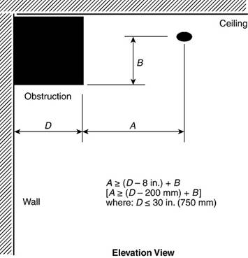
Figure 10.3.6.1.4(b) Obstruction Against Wall (Standard Sidewall Spray Sprinklers). (New Image)
-
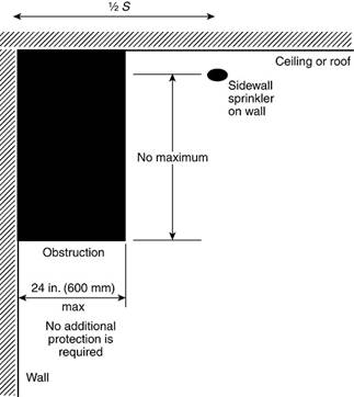
Figure 10.3.6.1.4(c) Obstruction Against Wall (Standard Sidewall Spray Sprinklers). (New Image)
- 10.3.6.1.7: Same text, different image: “Obstructions up to 12 in. (300 mm) in width in hallways up to 6 ft (1.8 m) in width shall be permitted in accordance with Figure 10.3.6.1.7 when the sprinkler is located in the allowable obstruction zone and the closest edge of the obstruction is a minimum of 12 in. (300 mm) away from the deflector.”
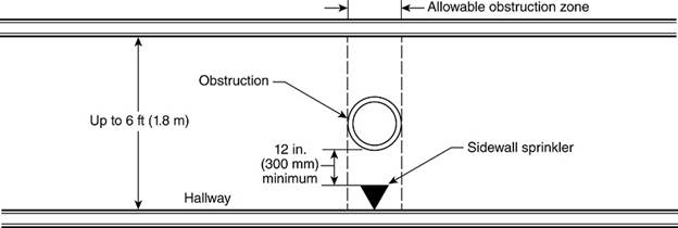
- 2022:
- 10.3.6.2.2.1 Privacy Curtains
- 2022:
- Privacy curtains in light hazard occupancies are not considered obstructions if:
- Supported by fabric mesh on a ceiling track.
- Mesh openings ≥70%.
- Mesh extends a minimum of 22 in (550 mm) down from the ceiling.
- 2025:
- Privacy curtains in light hazard occupancies are not considered obstructions if:
- Supported by fabric mesh on a ceiling track.
- Mesh openings ≥70%.
- Mesh extends a minimum of 20 in (500 mm) down from the sprinkler deflector.
- 2022:
10.3.6.3 Obstructions that Prevent Discharge Sidewall
- 2022:
- 10.3.6.3.1: “Continuous or noncontinuous obstructions that interrupt the water discharge in a horizontal plane more than 18 in. (450 mm) below the sprinkler deflector in a manner to limit the distribution from reaching the protected hazard shall comply with this section.”
- 10.3.6.3.2: “Sprinklers shall be installed under fixed obstructions over 4 ft (1.2 m) wide.”
- 2025:
- 10.3.6.3: “Supplemental sprinklers shall be installed below continuous or noncontinuous fixed obstructions over 4 ft (1.2 m) in width that interrupt the water discharge in a horizontal plane more than 18 in (450 mm) below the ceiling sprinkler deflector. (See A.9.5.5.3.1.)”
Chapter 11 – Installation Requirements for Extended Coverage Upright, Pendent, Sidewall Spray Sprinkler
11.2 Extended Coverage Upright and Pendent Spray Sprinklers.
11.2.1 Extended Coverage Sprinklers
2022: Extended coverage sprinklers could be installed only:
- In unobstructed construction, flat/smooth ceiling, slope ≤ 1 in 6.
- In unobstructed or noncombustible obstructed construction, where listed.
- Within trusses/bar joists with web ≤ 1 in, or trusses spaced > 7½ ft o.c., ceiling slope ≤ 1 in 6.
- Under smooth flat ceilings with slope ≤ 1 in 3 where specifically listed (upright/pendent).
- Sidewalls per §11.3.5.2.1 for slopes > 2 in 12.
- In each bay of obstructed construction consisting of solid structural members that extend below the deflector.
- To protect areas below a single overhead door(s).
2025: The only material tweak is in (6):
- “Extended coverage upright and pendent sprinklers installed in obstructed construction, in accordance with 11.2.4.1.”
11.2.1.1 New K-factor / ceiling height limitation (pendent heads) (New in 2025)
2022:
- No ceiling-height limitation in Chapter 11 specific to the K-factor of EC sprinklers in non-storage occupancies.
- Non-storage EC upright/pendent could, in principle, be used at any height, subject only to general listing/application limits.
2025: “Extended-coverage pendent sprinklers having a nominal K-factor of K-22.4 (K-320) or less shall not be permitted for use in Ordinary Hazard Group 2 and higher occupancy hazards where the ceiling height is greater than 30 ft (9.1 m).”
- Testing showed EC uprights with K-11.2 and K-14.0 could work in OH1 and OH2 above 30 ft.
- That performance was not demonstrated for pendent versions with K ≤ 22.4.
- This ties into the broader height limits for nonstorage occupancies in 19.2.3.2.5.
11.2.3 Sprinkler Spacing (Extended Coverage Upright and Pendent Spray Sprinklers).
- 11.2.3.4.3 (New in 2025): “Where sprinklers are installed in every channel formed by solid obstructed construction with the deflectors above the bottom of the structural members, the structural members shall be considered baffles in accordance with 11.2.3.4.2.”
11.2.4 Deflector position (Extended Coverage Upright and Pendent Spray Sprinklers).
- 11.2.4.2 Deflector Orientation
- 11.2.4.2.1:
- 2022: “Roofs and ceilings having a pitch not exceeding 2 in 12 (16.7 percent) are considered horizontal in the application of 11.2.4.2, and sprinklers shall be permitted to be installed with deflectors horizontal.”
- 2025: “Roofs and ceilings having a pitch not exceeding 2 in 12 (16.7 percent) are considered horizontal in the application of 11.2.4.2, and sprinklers installed under horizontal ceilings shall be permitted to be installed with deflectors parallel to the floor.”
- 11.2.4.2.1:
11.2.5 Obstructions to Sprinkler Discharge (Extended Coverage Upright and Pendent Spray Sprinklers).
11.2.5.3 Obstructions that prevent discharge from reaching hazard (2022 origin 11.2.5.3.1–3.5)
- 2022:
- 11.2.5.3.1 – Defined when horizontal plane obstructions > 18 in below deflector must be treated.
- 11.2.5.3.2 – Required sprinklers under fixed obstructions > 4 ft wide.
- 11.2.5.3.3 – Exempted non-fixed items (e.g., conference tables).
- 11.2.5.3.4 – Required intermediate-level/rack-type (or shielded) sprinklers under open gratings, to prevent cold solder from overhead sprinklers.
- 11.2.5.3.5 – Same intermediate-level/rack or shielding requirement for sprinklers under round ducts.
- 2025:
- “Continuous or noncontinuous obstructions that interrupt the water discharge in a horizontal plane more than 18 in. (450 mm) below the sprinkler deflector in a manner to limit the distribution from reaching the protected hazard shall comply with 9.5.3.3. (See A.9.5.5.3.1.)”
- So, all detailed requirements for fixed obstructions > 4 ft, treatment of conference tables, open grating, round ducts, etc., are now centralized in Chapter 9 instead of being repeated in Section 11.
11.3 Extended Coverage Sidewall Spray Sprinklers. (See 10.2.9.2.)
Added a commentary to the enhanced content “Unless the rationale for the extended coverage sprinkler requirements differs from those for standard sidewall sprinklers, commentary regarding related items in Section 10.3 is not repeated in Section 11.3.”
11.3.2 Where extended-coverage sidewall sprinklers can be used
2022: Extended coverage sidewall spray sprinklers could only be installed in:
- Light hazard occupancies with smooth, horizontal or sloped flat ceilings.
- Ordinary hazard occupancies with smooth, flat ceilings, where specifically listed.
- Unobstructed construction with smooth, flat ceilings, slope ≤ 1 in 6.
- Unobstructed or noncombustible obstructed construction, where specifically listed.
- Within trusses/bar joists with web members ≤ 1 in, or trusses spaced > 7½ ft OC, with ceiling slope ≤ 1 in 6.
- On sloped ceilings > 2 in 12 where installed per 11.3.6.2.2.
- In each bay of obstructed construction with solid structural members extending below the deflector.
- To protect areas below a single overhead door.
2025: The above eight permitted uses are retained, plus two new permitted applications:
- For the protection of exterior projections and similar structures.
- Under cars in car stackers and car lift systems, with sprinklers placed under each level of cars (with additional explanatory commentary in A.10.3.2(9)).
11.3.6.3 Obstructions that prevent discharge from reaching the hazard
- 2022:
- 11.3.6.3.1: Continuous or noncontinuous obstructions that interrupt the discharge in a horizontal plane more than 18 in (450 mm) below the deflector, and that limit distribution reaching the hazard, must comply with this section.
- 11.3.6.3.2: Sprinklers must be installed under fixed obstructions over 4 ft (1.2 m) wide.
- 11.3.6.3.3: Sprinklers are not required under obstructions that are not fixed in place, such as conference tables.
- 2025: The detailed sidewall-specific text is deleted and replaced with a pointer to the general rules:
- “Continuous or noncontinuous obstructions that interrupt the water discharge in a horizontal plane more than 18 in. (450 mm) below the sprinkler deflector in a manner to limit the distribution from reaching the protected hazard shall comply with 9.5.5.3.”
- All the detailed “fixed > 4 ft wide → sprinkler required underneath; movable tables → sprinkler not required” logic now lives in §9.5.5.3 for all sprinkler types, not repeated here.
Chapter 12 – Installation Requirements for Residential Sprinklers
12.1 General
12.1.7 Distances Between Sprinklers.
- 12.1.7.5: Two images removed, 12.1.7.5(a) and 12.1.7.5(b).
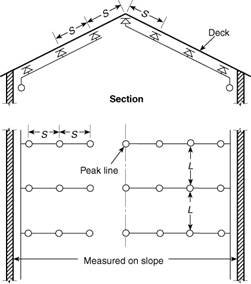
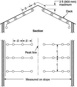
12.1.8 Deflector Position from Ceilings and Walls.
12.1.8.1.2(a) New Image: Position of sprinkler under beam
12.1.8.8 Deflector Orientation (Residential Sidewall Sprinklers). (New in 2025)
” Residential sidewall sprinklers, where installed under a sloped ceiling with a slope exceeding 2 in 12, shall be located in accordance with one of the following:”
- At the high point of the slope and positioned to discharge downward along the slope as shown in Figure 12.1.8.8(a)
- “Along slopes not exceeding 8 in 12 with the deflector installed parallel to the slope and positioned to discharge across the slope as shown in Figure 12.1.8.8(b)”
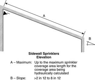
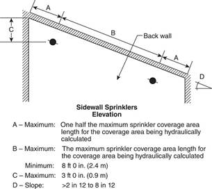
New Images: Figure 12.1.8.8(a) Sidewall Deflector Orientation with Discharge Parallel to the Slope & Figure 12.1.8.8(b) Sidewall Deflector Orientation with Discharge Perpendicular to the Slope.
12.1.10 Obstructions to Sprinkler Discharge (Residential Upright and Pendent Sprinklers).
12.1.10.3 Obstructions that Prevent Sprinkler Discharge from Reaching Hazard.
- 2022:
- 12.1.10.3.1: Obstructions > 18 in below deflector that block water must be addressed under 12.1.10.3.
- 12.1.10.3.2: Sprinklers required under fixed obstructions > 4 ft wide.
- 12.1.10.3.3: Sprinklers under open gratings must be shielded.
- 2025:
- 12.1.10.3 is now a single pointer:
- “Continuous or noncontinuous obstructions that interrupt the water discharge in a horizontal plane more than 18 in. (450 mm) below the sprinkler deflector in a manner to limit the distribution from reaching the protected hazard shall comply with 9.5.5.3. (See A.9.5.5.3.1.)”
- 12.1.10.3 is now a single pointer:
12.1.11 Residential Sidewall Obstructions
- 12.1.11.1.5 – Soffits and cabinets
- 2022 title: “Soffits and Cabinets.”
- 2025 title: “Soffits and Wall Cabinets.”
12.1.11.2 Pattern development obstructions
- 12.1.11.2.3 Shadow Areas for Residential Sidewalls (New in 2025)
- “Shadow areas created by walls and partitions shall be permitted in the protection area of a sprinkler as long as the cumulative areas do not exceed 15 ft2 (1.4 m2) per sprinkler.”
12.1.11.3 Obstructions preventing discharge from reaching hazard
- 2022:
- 12.1.11.3.1–3.5 detailed requirements:
- Sprinklers under fixed obstructions > 4 ft.
- Sprinklers under gratings shielded, etc.
- 12.1.11.3.1–3.5 detailed requirements:
- 2025:
- One line: obstructions > 18 in below deflector that limit distribution must comply with 9.5.5.3 (see A.9.5.5.3.1).
Chapter 13 – Installation Requirements for CMSA Sprinklers
13.2 CMSA Sprinklers
13.2.1.2 Ceiling slope limit (New in 2025) “CMSA sprinklers shall be installed only in buildings where the roof or ceiling slope does not exceed 4 in 12.”
13.2.5 Sprinkler Spacing (CMSA Sprinklers)
13.2.5.4 Minimum Distance Between Sprinklers.
- 13.2.5.4.2 Channels in solid obstructed construction
- “Where sprinklers are installed in every channel formed by solid obstructed construction with the deflectors above the bottom of the structural members, sprinklers in adjacent channels shall be permitted to be placed less than 8 ft (2.4 m) on center.”
- 2022: No equivalent allowance. Minimum spacing 8 ft OC unless using baffles (13.2.6.4.1) or simply not possible.
- 2025: If:
- You have solid obstructed construction forming channels,
- Sprinklers are installed in every channel, and
- Deflectors are above the bottom of the structural members,
Then you may go < 8 ft between sprinklers in adjacent channels, using the structural members as “natural baffles.
13.2.6 Deflector Position (CMSA Sprinklers).
13.2.6.1 Distance Below Ceilings:
- 2022:
- Unobstructed: deflector 6–8 in below ceiling.
- Obstructed: three options:
- 6–12 in below ceiling.
- For joists, etc.: within 1–6 in below joist bottom, up to 22 in to deck, with extra pressure under open wood joist.
- For concrete tees: deflector at or above 1 in below tee stems, with tees <7′-6″ apart, >3 ft on centers, and “regardless of depth,” but must comply with CMSA obstruction table.
- 2025:
- 13.2.6.1.2 Obstructed construction
- The obstructed rules have been expanded and segmented by ceiling slope, with an explicit note about “≤ 50% open” vs “> 50% open.”
- Enhanced content clarifies:
- These new rules are driven by FPRF sloped storage testing.
- Obstructed construction covered here is limited to ≤ 50% open. If > 50% open, treat as “unobstructed” per 13.2.6.1.2.4.
- 13.2.6.1.2.1 Obstructed Construction for Ceilings with Slopes Not Exceeding 1 in 12.
- “Sprinklers shall be installed in each individual channel of obstructed construction with the deflectors located a minimum of 6 in. (150 mm) and a maximum of 12 in. (300 mm) below the ceiling/roof deck.”
- “Where the maximum depth of the noncombustible structural members, including concrete tees, is 18 in. (450 mm), sprinkler deflectors shall be permitted to be installed within a horizontal plane not exceeding 6 in. (150 mm) vertically below the bottom of the noncombustible structural members.”
- “Where the maximum depth of the noncombustible structural members, including concrete tees, is greater than 18 in. (450 mm) but does not exceed 24 in. (600 mm), sprinkler deflectors shall be permitted to be installed within a horizontal plane not exceeding 6 in. (150 mm) vertically below the bottom of the noncombustible structural members only when the channels formed by obstructed construction are provided with blocking to the full depth of the noncombustible structural member with material equivalent to the structural member’s construction so that individual channel volumes do not exceed 400 ft3 (11.3 m3).”
- “Where wood joists or composite wood joists are provided with blocking to the full depth of the joists with material equivalent to or less combustible than the web construction so that individual channel volumes do not exceed 400 ft3 (11.3 m3), sprinkler deflectors shall be permitted to be installed within a horizontal plane not exceeding 6 in. (150 mm) vertically below the bottom of the joists only when a maximum distance of 22 in. (550 mm) can be maintained between the sprinkler deflector and the ceiling/roof deck.”
“Where the slope of the ceiling does not exceed 1 in 12, the sprinkler deflector shall be located in accordance with one of the following arrangements:”
- 13.2.6.1.2.2 Obstructed Construction Less than or Equal to 50 Percent Open for Ceilings with Slopes Not Exceeding 2 in 12.
- “Sprinklers shall be installed in each individual channel of obstructed construction with the deflectors located a minimum of 6 in. (150 mm) and a maximum of 12 in. (300 mm) below the ceiling/roof deck.”
- “Where the maximum depth of the noncombustible structural members, including concrete tees, is 12 in. (300 mm), sprinkler deflectors shall be permitted to be installed within a horizontal plane not exceeding 6 in. (150 mm) vertically below the bottom of the noncombustible structural members.”
- “Where the maximum depth of the noncombustible structural members, including concrete tees, is greater than 12 in. (300 mm) but does not exceed 24 in. (600 mm), sprinkler deflectors shall be permitted to be installed within a horizontal plane not exceeding 6 in. (150 mm) vertically below the bottom of the noncombustible structural members only when the channels formed by obstructed construction are provided with blocking to the full depth of the noncombustible structural member with material equivalent to the structural member’s construction so that individual channel volumes do not exceed 400 ft3 (11.3 m3).”
- “Where wood joists or composite wood joists are provided with blocking to the full depth of the joists with material equivalent to or less combustible than the web construction so that individual channel volumes do not exceed 400 ft3 (11.3 m3), sprinkler deflectors shall be permitted to be installed within a horizontal plane not exceeding 6 in. (150 mm) vertically below the bottom of the joists only when a maximum distance of 22 in. (550 mm) can be maintained between the sprinkler deflector and the ceiling/roof deck.”
“Where the slope of the ceiling is greater than 1 in 12, but does not exceed 2 in 12, the sprinkler deflector shall be located in accordance with one of the following arrangements:”
- 13.2.6.1.2.3 Obstructed Construction Less than or Equal to 50 Percent Open for Ceilings with Slopes Not Exceeding 4 in 12.
“Where the slope of the ceiling is greater than 2 in 12, but does not exceed 4 in 12, the sprinkler deflector shall be located in accordance with one of the following arrangements:”
- “Sprinklers shall be installed in each individual channel of obstructed construction with the deflectors located a minimum of 6 in. (150 mm) and a maximum of 12 in. (300 mm) below the ceiling/roof deck.”
- “Where the maximum depth of the structural members, including concrete tees, is 12 in. (300 mm) and are installed perpendicular to the ceiling slope, sprinkler deflectors shall be permitted to be installed within a horizontal plane not exceeding 6 in. (150 mm) vertically below the bottom of the structural members only when the channels formed by obstructed construction are provided with blocking to the full depth of the structural member with material equivalent to or less combustible than the structural member’s construction so that individual channel volumes do not exceed 300 ft3 (8.5 m3).”
- 13.2.6.1.2.4 Obstructed Construction Greater than 50 Percent Open.
“Where the slope of the ceiling is greater than 1 in 12 under obstructed construction that is greater than 50 percent open, sprinklers shall be installed in accordance with the rules for unobstructed construction.”
13.2.7 Obstructions to Sprinkler Discharge (CMSA Sprinklers).
- 2022 (13.2.8):
- Had its own CMSA-specific obstruction framework, including:
- Table 13.2.8.1.2(a)/(b) (allowable distance above/beside obstructions).
- 36 in “pattern development” zone below sprinklers where obstructions must be evaluated.
- Three-times-rule for obstructions ≤8 in wide.
- Special rules for branch lines (sprinklers directly on branch lines ≤4 in diameter vs sprigs/offsets for >4 in).
- Tables 13.2.8.3.2(a)/(b) for obstructions entirely below sprinklers, with required A/B distances.
- Specific diagrams for obstructions 24 in below, more than 24 in below, parallel to branch lines, etc.
- Had its own CMSA-specific obstruction framework, including:
- 2025:
- 13.2.7.1 General
- 13.2.7.1.1: “In addition to the requirements of 9.5.5, CMSA sprinklers shall be arranged in accordance with 13.2.7 to minimize obstruction to their discharge pattern, or supplemental sprinklers shall be provided to ensure adequate coverage of the hazard.”
- 13.2.7.1.2: “CMSA sprinklers with a special obstruction allowance shall be installed according to their listing.”
- 13.2.7.2 Obstructions to pattern development
- 13.2.7.2.1: “In addition to the requirements of 13.2.7.2.2, CMSA sprinklers shall be arranged in accordance with 14.2.10.2 to minimize obstruction to the development of their discharge pattern.”
- 13.2.7.2.2: “Unless the requirements of 14.2.10.2 are met, for obstructions 8 in. (200 mm) wide or less in width, as shown in Figure 13.2.7.2.2, sprinklers shall be positioned such that they are located at least a distance three times greater than the maximum dimension of the obstruction from the sprinkler.”
- 13.2.7.3 Obstructions that prevent discharge from reaching hazard
- “CMSA sprinklers shall be arranged in accordance with 14.2.10.3 to minimize obstruction to sprinkler discharge reaching the hazard. (See A.9.5.5.3.1.)”
- Major structural change; many 2022 CMSA-only obstruction rules are removed from Chapter 13 and replaced with cross-references to the ESFR obstruction framework in Chapter 14 plus the three-times rule.
- 13.2.7.1 General
13.2.8 Clearance to storage (was 13.2.9)
Chapter 14 – Installation Requirements for Early Suppression Fast-Response Sprinklers
14.2 Early Suppression Fast-Response Sprinklers
14.2.3 Roof / Ceiling Slope Limit
2022:
- ESFR sprinklers permitted only where roof or ceiling slope does not exceed 2 in 12.
2025:
- ESFR sprinklers permitted where roof or ceiling slope does not exceed 4 in 12.
14.2.6 Occupancy and Hazard (2022 Origin 14.2.7)
2022:
- ESFR permitted in light and ordinary hazard occupancies if listed.
- Additional allowances:
- 14.2.7.2: Protection area permitted to follow Ch. 10.
- 14.2.7.3: Spacing permitted to follow Ch. 10.
- 14.2.7.4: Obstruction rules permitted to follow 10.2.7.2.
2025:
- 14.2.6.1: “When ESFR sprinklers are used for the protection of light or ordinary hazard occupancies, the obstruction to the sprinkler discharge pattern of ESFR sprinklers shall be permitted to meet the obstruction discharge requirements of 10.2.8.2.”
14.2.7 Protection Areas per Sprinkler (2022 Origin 14.2.8)
14.2.7.2 Maximum Protection Area of Coverage.
14.2.7.2.3 Sprinkler Movement to Avoid Obstructions (2022 Origin 14.2.8.2.3 & 14.2.8.2.4)
- 2022 14.2.8.2.3* (Moving an individual sprinkler)
- Applies where obstructions created by structural elements (e.g., trusses, bar joists, wind bracing) interfere with sprinkler placement.
- A single sprinkler may be moved along the branch line up to 1 ft (300 mm) from its allowable spacing.
- Coverage of the moved sprinkler ≤ 110 ft².
- Average actual floor area of the moved sprinkler and adjacent sprinklers ≤ 100 ft².
- Adjacent branch lines must maintain the same pattern.
- Maximum distance between sprinklers ≤ 12 ft.
- 2022 14.2.8.2.4 (Moving an entire branch line)
- Same obstruction basis as 14.2.8.2.3 (structural elements).
- One entire branch line may be moved up to 1 ft (300 mm) from its allowable spacing.
- Coverage for sprinklers on the moved branch line and the adjacent branch line ≤ 110 ft² per sprinkler.
- Average actual floor area ≤ 100 ft².
- Maximum distance between sprinklers ≤ 12 ft.
- Branch lines cannot be moved if there are already moved sprinklers that exceed maximum spacing.
- 2025:
- “Where obstructions that prevent sprinkler discharge from reaching the hazard exist, ceiling sprinklers shall be permitted to exceed their maximum allowable spacing to avoid these obstructions as follows:”
- “The linear spacing of the obstructed sprinkler, in the direction the sprinkler is moved, shall not exceed 1 ft (0.3 m) beyond the maximum allowable linear spacing.”
- “The linear spacing of the obstructed sprinkler, in the direction the sprinkler is moved, shall not exceed 12 ft (3.7 m).”
- “The area of coverage of the obstructed sprinkler shall not exceed 110 ft2 (10 m2).”
- “Where the obstructed sprinkler has been moved in a direction along the branch line, the linear and area spacing of the sprinklers on either side of the obstructed sprinkler along the branch line shall comply with the allowable sprinkler spacing requirements.”
- “Where the obstructed sprinkler has been moved in a direction between the branch lines, the linear spacing and area of coverage of the sprinklers on either side of the obstructed sprinkler between the branch lines shall comply with the allowable sprinkler spacing requirements.”
- Applies where obstructions prevent sprinkler discharge from reaching the hazard.
- Not limited to “structural elements” language; framed around discharge effectiveness.
- A ceiling sprinkler may exceed maximum allowable spacing to avoid the obstruction.
- Linear spacing in the direction of movement:
- ≤ 1 ft beyond maximum allowable spacing.
- ≤ 12 ft total.
- Coverage of the obstructed sprinkler ≤ 110 ft².
- No average-area requirement stated.
- Compliance depends on direction of movement:
- Along branch line: sprinklers on either side along the branch line must comply.
- Between branch lines: sprinklers on either side between branch lines must comply.
- “Where obstructions that prevent sprinkler discharge from reaching the hazard exist, ceiling sprinklers shall be permitted to exceed their maximum allowable spacing to avoid these obstructions as follows:”
14.2.8 Sprinkler Spacing (2022 Origin 14.2.9)
14.2.8.4.3 Structural Members Acting as Baffles (New in 2025)
2022:
- Channelized construction rules scattered across 14.2.4 and 14.2.9.
- Structural members implicitly treated as separators.
2025:
- “Where sprinklers are installed in every channel formed by solid obstructed construction with the deflectors above the bottom of the structural members, the structural members shall be considered baffles in accordance with 14.2.8.4.2.”
14.2.9 Deflector Position (Early Suppression Fast-Response Sprinklers).
14.2.9.1 Distance Below Ceilings. (K-factor based distance below ceiling)
2022:
- 14.2.10.1.1: Pendent K-14 / K-16.8 / K-28: 6–14 in.
- 14.2.10.1.2: Pendent K-22.4 / K-25.2 / K-33.6: 6–18 in.
- 14.2.10.1.3: Upright K-14 / K-16.8: 3–12 in.
- 14.2.10.1.4: With obstructed construction, branch lines permitted across beams, but sprinklers in bays, not under beams.
2025:
- 14.2.9.1.1 Unobstructed construction
- “Where nominal K-14.0 (K-200), K-16.8 (K-240), and K-28.0 (K-400) pendent sprinklers are installed under unobstructed construction, the deflectors shall be positioned a minimum 6 in. (150 mm) and a maximum of 14 in. (350 mm) below the ceiling/roof deck.”
- “Where nominal K-22.4 (K-320), K-25.2 (K-360), and K-33.6 (K-480) pendent sprinklers are installed under unobstructed construction, the deflectors shall be positioned a minimum 6 in. (150 mm) and a maximum of 18 in. (450 mm) below the ceiling/roof deck.”
- “Where nominal K-14.0 (K-200) and K-16.8 (K-240) upright sprinklers are installed under unobstructed construction, the deflectors shall be positioned a minimum of 3 in. (75 mm) and a maximum of 12 in. (300 mm) below the ceiling/roof deck.”
- 14.2.9.1.2 Obstructed construction
- 2025 turns the “obstructed construction” deflector positioning into a decision tree; it introduces a structured, conditional framework allowing alternate deflector planes depending on:
- percent open (≤ 50% open vs > 50% open),
- ceiling slope bands (≤1:12, >1:12–≤2:12, >2:12–≤4:12),
- structural member depth thresholds (12 in / 18 in / 24 in),
- blocking and channel volume caps (400 ft³ for some cases; 300 ft³ for the steeper/specific orientation case),
- member orientation (perpendicular to slope in the 4:12 case).
- 14.2.9.1.2.1 Obstructed Construction Less than or Equal to 50 Percent Open for Ceilings with Slopes Not Exceeding 1 in 12.
“Where the slope of the ceiling does not exceed 1 in 12, the sprinkler deflector shall be located in accordance with one of the following arrangements:”
- “Sprinklers shall be installed in each individual channel of obstructed construction with the deflectors located below the ceiling/roof deck in accordance with 14.2.9.1.1.”
- “Where the maximum depth of the structural members, including concrete tees, is 18 in. (450 mm), sprinkler deflectors shall be permitted to be installed within a horizontal plane not exceeding 6 in. (150 mm) vertically below the bottom of the structural members.”
- “Where the maximum depth of the structural members, including concrete tees, is greater than 18 in. (450 mm) but does not exceed 24 in. (600 mm), sprinkler deflectors shall be permitted to be installed within a horizontal plane not exceeding 6 in. (150 mm) vertically below the bottom of the structural members only when the channels formed by obstructed construction are provided with blocking to the full depth of the structural member with material equivalent to or less combustible than the structural member’s construction so that individual channel volumes do not exceed 400 ft3 (11.3 m3).”
- 2025 turns the “obstructed construction” deflector positioning into a decision tree; it introduces a structured, conditional framework allowing alternate deflector planes depending on:
- 14.2.9.1.2.2 Obstructed Construction Less than or Equal to 50 Percent Open for Ceilings with Slopes Not Exceeding 2 in 12.
- “Sprinklers shall be installed in each individual channel of obstructed construction with the deflectors located below the ceiling/roof deck in accordance with 14.2.9.1.1.”
- “Where the maximum depth of the structural members, including concrete tees, is 12 in. (300 mm), sprinkler deflectors shall be permitted to be installed within a horizontal plane not exceeding 6 in. (150 mm) vertically below the bottom of the structural members.”
- “Where the maximum depth of the structural members, including concrete tees, is greater than 12 in. (300 mm) but does not exceed 24 in. (600 mm), sprinkler deflectors shall be permitted to be installed within a horizontal plane not exceeding 6 in. (150 mm) vertically below the bottom of the structural members only when the channels formed by obstructed construction are provided with blocking to the full depth of the structural member with material equivalent to or less combustible than the structural member’s construction so that individual channel volumes do not exceed 400 ft3 (11.3 m3).”
“Where the slope of the ceiling is greater than 1 in 12, but does not exceed 2 in 12, the sprinkler deflector shall be located in accordance with one of the following arrangements:”
- “Where the slope of the ceiling is greater than 2 in 12, but does not exceed 4 in 12, the sprinkler deflector shall be located in accordance with one of the following arrangements:”
- “Sprinklers shall be installed in each individual channel of obstructed construction with the deflectors located below the ceiling/roof deck in accordance with 14.2.9.1.1.”
- “Where the maximum depth of the structural members, including concrete tees, is 12 in. (300 mm) and the structural members are installed perpendicular to the ceiling slope, sprinkler deflectors shall be permitted to be installed within a horizontal plane not exceeding 6 in. (150 mm) vertically below the bottom of the structural members only when the channels formed by obstructed construction are provided with blocking to the full depth of the structural member with material equivalent to or less combustible than the structural member’s construction so that individual channel volumes do not exceed 300 ft3 (8.5 m3).”
- “Where the slope of the ceiling is greater than 1 in 12 under obstructed construction that is greater than 50 percent open, sprinklers shall be installed in accordance with the rules for unobstructed construction.”
14.2.9.2 Deflector orientation
2022:
- “Deflectors … aligned parallel to ceilings or roofs.”
2025:
- “Deflectors … aligned in accordance with 9.5.4.3.”
14.2.10 Obstructions to Sprinkler Discharge (Early Suppression Fast-Response). (2022 Origin 14.2.11)
14.2.10.1 General (2025)
- 2022 equivalent:
- The “obstruction rules” were primarily in 14.2.11, but the “high-piled adjacency trigger” was in a different place:
- 14.2.11.2(8): apply obstruction criteria (there, 14.2.11.2) to ceiling sprinklers within 6 ft horizontally of any high-piled storage (same “not physically separated” condition).
- Also, 2022 repeated “special obstruction allowance per listing” in multiple sub-sections: 14.2.11.1.3, 14.2.11.2(6), 14.2.11.3.7.
- 2025:
- 14.2.10.1.1 Adds: “In addition to the requirements of 9.5.5, ESFR sprinklers shall be arranged in accordance with 14.2.10 to minimize obstruction to their discharge pattern, or supplemental sprinklers shall be provided to ensure adequate coverage of the hazard.”
- 14.2.10.1.2 (2022 Origin 14.2.11.1.3): “ESFR sprinklers with a special obstruction allowance shall be installed according to their listing.”
- 14.2.10.1.3 (2022 Origin 14.2.11.2(8)): “Where high-piled storage is not physically separated from an adjacent light or ordinary hazard area, the sprinkler obstruction criteria of 14.2.10 shall apply to all ceiling sprinklers located within 15 ft (4.6 m) horizontally of any high-piled storage.”
14.2.10.2 Obstructions to Sprinkler Discharge Pattern Development (2025)
- 2022 equivalent 14.2.11.1.2: only covered the <24 in obstruction condition. “The requirements of 14.2.11.1.1 shall not apply where sprinklers are spaced on opposite sides of obstructions less than 24 in. (600 mm) wide, provided the distance from the centerline on the obstructions to the sprinklers does not exceed one-half the allowable distance between sprinklers.”
- 2025:
- Added condition number 2 for the exception of table rules. Table rules do not apply where one of the following conditions is satisfied:
- “Sprinklers are spaced on opposite sides of an obstruction less than 24 in. (600 mm) wide, provided the distance from the centerline of the obstruction to the sprinklers does not exceed one-half the allowable distance between sprinklers.”
- “Supplemental sprinklers have been installed under the obstruction.”
- Added condition number 2 for the exception of table rules. Table rules do not apply where one of the following conditions is satisfied:
14.2.10.2.3 Sprinkler Pipe
2022 equivalent: 14.2.11.3.3 Branchlines
- Same structure, except the horizontal offset was min 12 in (not 6 in) from the pipe.
2025:
- “Offset horizontally a minimum of 6 in. (150 mm) from the sprinkler pipe”
14.2.10.3 Obstructions that Prevent Sprinkler Discharge from Reaching Hazard
14.2.10.3.1 (New in 2025)
- Obstructions, continuous or noncontinuous, individual or grouped, that interrupt the water discharge in a horizontal plane below the sprinkler deflector in a manner to limit the distribution from reaching the protected hazard shall comply with 14.2.10.3.
14.2.10.3.2 (2022 equivalent 14.2.11.3.4)
14.2.10.3.3 (New in 2025)
- Supplemental sprinklers shall be installed under obstructions entirely below ceiling sprinklers where obstruction interferes with discharge reaching hazard.
14.2.10.3.4 When supplemental sprinklers NOT required
2025:
- “Supplemental sprinklers shall not be required below obstructions when the obstruction or occupancy is in accordance with one of the following:”
- “The obstruction is 11⁄2 in. (38 mm) or less in width and is located a minimum of 12 in. (300 mm) below the elevation of the sprinkler deflector.” (2022 equivalent 14.2.11.3.1(2))
- “The obstruction is 6 in. (150 mm) or less in width and is located a minimum of 6 in. (150 mm) horizontally from the sprinkler.” (2022 equivalent 14.2.11.3.1(3))
- “The obstruction is 24 in. (600 mm) or less in width and is located a minimum of 12 in. (300 mm) horizontally from the sprinkler.” (2022 equivalent 14.2.11.3.1(4))
- “The obstruction is 4 in. (100 mm) or less in width, and is located entirely below the sprinkler pipe connected to the ceiling sprinkler, and the ceiling sprinkler is upright.” (New in 2025)
- “The occupancy is protected in accordance with 14.2.6, and obstructions comply with 9.5.5.3.” (2022 equivalent 14.2.11.3.1(6))
14.2.10.3.5 Supplemental sprinkler spacing (2025)
14.2.10.3.5.1 (New in 2025)
- “When supplemental sprinklers are required, in addition to the requirements of 9.5.5.3.3 the spacing of supplemental sprinklers under obstructions shall be in accordance with one of the following:”
- “Where supplemental sprinklers are required below non-flat or non-solid obstructions, the sprinklers shall be located no more than 2 ft (0.6 m) horizontally from the edges of the obstruction and be installed using linear and area spacing that does not exceed 4 ft (1.2 m) and 16 ft2 (1.5 m2), respectively.”
- “Where supplemental sprinklers are required below flat, solid obstructions not exceeding 2 ft (0.6 m) in width, the maximum allowable linear spacing for the sprinklers shall be 8 ft (2.4 m).”
- “Where a flat, solid continuous horizontal barrier having the same footprint of the obstruction is installed below an obstruction not exceeding 2 ft (0.6 m) in width, the maximum allowable linear spacing for the sprinklers shall be 8 ft (2.4 m).”
- “Where supplemental sprinklers are required below flat, solid obstructions greater than 2 ft (0.6 m), but not exceeding 10 ft (3.0 m) in width, the maximum allowable linear spacing for the sprinklers shall be 10 ft (3.0 m).”
- “Where a flat, solid continuous horizontal barrier having the same footprint of the obstruction is installed below an obstruction greater than 2 ft (0.6 m), but not exceeding 10 ft (3.0 m) in width, the maximum allowable linear spacing for the sprinklers shall be 10 ft (3.0 m).”
- “Where supplemental sprinklers are required below flat, solid obstructions greater than 10 ft (3.0 m) in width, the supplemental sprinkler spacing shall be in accordance with the sprinkler’s spacing requirements for when the sprinkler is installed under unobstructed construction.”
- “Where a flat, solid continuous horizontal barrier having the same footprint of the obstruction is installed below an obstruction greater than 10 ft (3.0 m) in width, the supplemental sprinkler spacing shall be in accordance with the sprinkler’s spacing requirements for when the sprinkler is installed under unobstructed construction.”
14.2.10.3.5.2 (New in 2025)
- “When supplemental sprinklers are installed in accordance with 14.2.10.3.5.1, supplemental sprinklers shall not be required to be equipped with water shields.”
Chapter 15 – Installation Requirements for Special Sprinklers
15.1 Open Sprinklers and Open Nozzles
2022:
- Title: “Open Sprinklers”
2025:
- Title expanded to “Open Sprinklers and Open Nozzles”
15.1.3 (New in 2025)
- Where open sprinklers or open nozzles are used and automatic activation is achieved by hydraulic, pneumatic, or other means, the deflector of the open sprinklers or nozzles shall be permitted to exceed the maximum distance below the ceiling indicated in the applicable section for that style of sprinkler.
15.2 Special Sprinklers
15.2.1 Listing and Evaluation Criteria
- 2022:
- Special sprinklers that are intended for the protection of specific hazards or construction features shall be permitted where such devices have been evaluated and listed for performance under the following conditions:
- Fire tests
- Spray pattern wetting (floors/walls)
- Obstructions
- Thermal sensitivity
- Performance under horizontal or sloped ceilings
- Area of design
- Allowable clearance to ceilings
- Special sprinklers that are intended for the protection of specific hazards or construction features shall be permitted where such devices have been evaluated and listed for performance under the following conditions:
- 2025
- Special sprinklers that are intended for the protection of specific hazards or construction features shall be permitted where such devices have been evaluated and listed for performance under the following conditions:
- Fire tests
- Spray pattern wetting (floors/walls)
- Obstructions
- Thermal sensitivity
- Performance under horizontal or sloped ceilings
- Hydraulic design criteria (replaces “area of design”)
- Allowable clearance to ceilings
- Special sprinklers that are intended for the protection of specific hazards or construction features shall be permitted where such devices have been evaluated and listed for performance under the following conditions:
15.2 Special Sprinklers
15.2.3 Manufacturer’s Listing Basis (New in 2025)
- “Where special sprinklers are listed for protection of features, system design shall be based on the listing requirements identified in the manufacturer’s instructions for the individual sprinkler being used, unless otherwise approved.”
15.2.4 Equivalent Protection Schemes (New in 2025)
- “Listed sprinklers that have been tested at an approved testing laboratory for specific special use conditions as indicated in 15.2.1(1) through 15.2.1(7) as applicable shall be permitted to be used for equivalent fire protection schemes developed in accordance with Section 1.5 where acceptable to the AHJ.”
- Annex: “The development and use of test data to evaluate special use conditions at an approved testing laboratory that evaluate the performance of listed sprinklers under special use conditions can be used as a basis to demonstrate the equivalency of a proposed usage.”
Chapter 16 – Installation of Piping, Valves, and Appurtenances
16.1 Basic Requirements
16.1.3 Reconditioned Components
- 2022: “The use of reconditioned valves and devices shall not be permitted in new systems.”
- 2025: “The use of reconditioned valves and devices shall not be permitted in new systems.”
16.2 Sprinkler Installation
16.2.7 Stock of Spare Sprinklers.
- 16.2.7.1:
- Annex adds: “It is the intent of this section to require spare sprinklers and associated manufacturer’s sprinkler wrenches based on the facility as opposed to individual buildings or systems. Spare sprinklers for campus arrangements such as schools, hospitals, or multifamily complexes should be located under the owner’s control and are not necessarily required to be provided at each building or riser location. A sufficiently sized cabinet(s) capable of meeting the requirements for a single building is adequate. The spare sprinkler cabinet should contain all the various types found on the property based on in the quantities prescribed in Chapter 16.”
- 16.2.7.2:
- 2022: “The sprinklers shall correspond to the types and temperature ratings of the sprinklers in the property.”
- 2025: “The sprinklers shall correspond to the types, orientations, and temperature ratings of the sprinklers in the property.”
- 16.2.7.5:
- 2022: “The stock of spare sprinklers shall include all types, orientations, and ratings installed and shall be as follows:”
- 2025: “The stock of spare sprinklers shall include all types, orientations, and ratings installed and shall be as follows:”
- 16.2.7.7: “A list of the sprinklers installed in the property shall be posted in the sprinkler cabinet.”
- 2022:
- Sprinkler Identification Number (SIN) if equipped; or the manufacturer, model, K-factor, deflector type, thermal sensitivity, and pressure rating
- General description
- Quantity of each type to be contained in the cabinet
- Issue or revision date of the list
- 2025:
- Sprinkler identification number (SIN), if equipped, the manufacturer, model, K-factor, deflector type, thermal sensitivity, pressure rating, and temperature rating
- Manufacturer’s sprinkler wrench model number for each sprinkler type
- General description
- Quantity of each type of sprinkler installed in the property
- Quantity of each type of sprinkler to be contained in the cabinet
- Issue or revision date of the list
- 2022:
16.3 Piping Installation
16.3.1 General
- 2022: Material-by-material routing statement (Steel per 16.3.2/3/4; Copper per 16.3.5; Nonmetallic per 16.3.9; Brass per 16.3.6; Stainless per 16.3.7).
- 2025: 16.3.1 replaces that with one broad sentence: “Sprinkler piping shall comply with the requirements of this section.”
16.3.2* Steel Pipe – Welded or Roll-Grooved
16.3.2.1 (New in 2025)
- “Black and galvanized pipe sizes shall be no less than 1 in. (25 mm) nominal.”
16.3.2.2 (2022 Renumbered 16.3.2)
16.3.3 Steel Pipe – Threaded.
- 16.3.3.1 (NEW in 2025)
- “Black and galvanized pipes sizes shall be no less than 1 in. (25 mm) nominal.”
- 16.3.3.2 (2022 Renumbered 16.3.3)
16.3.4 Nonmetallic Pipe (New in 2025)
- 16.3.4.1: “Nonmetallic pipe shall be in accordance with 16.3.10.”
- 16.3.4.2: “Nonmetallic pipe shall be no less than 3/4 in. (20 mm) nominal.”
16.3.6 Copper Tube
- 16.3.6.1 (New in 2025): “Copper tube shall be no less than 3⁄4 in. (20 mm) nominal.”
- 16.3.6.2 (2022 Renumbered 16.3.5)
16.3.7 Brass Pipe
- 16.3.7.1 (New in 2025): “Brass pipe shall be no less than 3⁄4 in. (20 mm) nominal.”
- 16.3.7.2 (2022 Renumbered 16.3.6)
16.3.8 Stainless Steel Pipe
Status: Modified (new minimum nominal size rule + renumbered schedule rule).
- 16.3.8.1 (New in 2025): Stainless steel pipe shall be no less than 3⁄4 in. (20 mm) nominal.
- 16.3.8.2 (2022 Renumbered 16.3.7)
16.3.9 Metallic Pipe and Tube Bending
- 16.3.9.2:
- 2022 (16.3.8.2): “For Schedule 40 and copper tubing…”
- 2025: “For Schedule 40 steel pipe and Types K and L copper tubing…” This is largely clarifying, not changing the engineering intent.
16.3.13 Piping to Sprinklers Below Ceilings
Status: Modified (scope narrowed + renumbered).
2022 (16.3.12.1):
- “In new installations expected to supply sprinklers below a ceiling, minimum 1 in. (25 mm) outlets shall be provided.”
2025:
- “In new installations expected to supply sprinklers below a ceiling utilizing black or galvanized steel piping, minimum 1 in. (25 mm) outlets shall be provided.”
16.4 Protection of Piping
16.4.1 Protection of Piping Against Freezing
16.4.1.1.1*
- 2022: “The weather temperature used to determine if an unheated portion of a system is subject to freezing and required to be protected in accordance with 16.4.1.1 shall be the lowest mean temperature for one day, obtained from an approved source.”
- 2025: “The weather temperature used to determine if a portion of a system is subject to freezing and required to be protected in accordance with 16.4.1.1 shall be the average annual extreme minimum temperature, obtained from an approved source.”
16.4.2 Protection of Piping Against Corrosion
2022:
- 16.4.2.1: corrosive conditions → corrosion-resistant materials or protective coating
- 16.4.2.2: unusual corrosive properties → CRR ≥ 1 and treat per 5.1.4
- 16.4.2.3: corrosive conditions or weather exposure → corrosion-resistant materials/coatings
- 16.4.2.4: underground steel pipe → protect against corrosion
2025:
- 16.4.2.1: same basic “corrosive conditions” rule (plus new commentary about oceanfront salt spray; and reminder coatings not allowed on sprinklers in field)
- 16.4.2.2 (2022 Renumbered 16.4.2.3)
- 16.4.2.3 (2022 Renumbered 16.4.2.4)
- 16.4.2.4 (New in 2025): “Where conditions that contribute to MIC are found or known to exist, the owner(s) shall notify the sprinkler system installer and develop a plan to treat the system using one of the following methods:”
- “Install system piping that will not be affected by the MIC microbes.”
- “Treat all water that enters the system using a listed bacterial inhibitor.”
- “Implement an approved plan for monitoring the interior conditions of the pipe at established time intervals and locations.”
- “Install a corrosion monitoring station and monitor at established intervals”
- 16.4.2.5 (New in 2025): “Where conditions are found or are known to exist that contribute to unusual corrosive properties, the owner(s) shall notify the sprinkler system installer, and a plan shall be developed to treat the system using at least one of the following methods:”
- “Install system piping that is corrosion resistant.”
- “Treat water that enters the system using a listed corrosion inhibitor.”
- “Implement an approved plan for monitoring the interior conditions of the pipe at established intervals and locations.”
- “Install approved corrosion monitoring stations and monitor at established intervals.”
- “Fill dry-pipe or preaction systems with at least 98 percent pure nitrogen in lieu of air to mitigate against corrosion.”
- “Use a listed nitrogen generator that is sized and installed in accordance with the manufacturer’s instructions.”
- “Use a listed vapor corrosion inhibitor delivery system sized and installed in accordance with the manufacturer’s instructions.”
- 16.4.2.6 (2022 Renumbered 16.4.2.2).
16.4.4 Protection of Piping Subject to Mechanical Damage
Status: Modified (expanded scope + new plate extension requirement).
2022:
- Applied when pipe other than steel run horizontally or vertically through wood or metal studs, with shield plates when pipe face < 1.25 in. from edge; plate thickness; cover notched/bored area.
2025:
- “Where concealed pipe other than steel is installed through holes or notches in studs, joists, rafters, or similar members less than 1.25 in. (32 mm) from the nearest edge of the member, the following provisions shall apply:”
- Keeps plate thickness and “cover the area” requirement.
- Adds “(4) Steel shield plates shall extend a minimum of 2 in. (50 mm) along the member.”
- Annex: “Nail plates should only cover the stud or structural member that the pipe is penetrating — the nail plate should not extend past the width of the member. Only the length of the nail plate along the member should be extended a minimum of 2 in. (50 mm).”
16.8 Fitting Installation
16.8.8 Flexible Sprinkler Hose Fitting Length (New in 2025)
- 16.8.8.1:
- “Flexible sprinkler hose fittings shall not exceed 12 ft (3.7 m) in length when installed above a rigid ceiling.”
- Annex: “Rigid ceilings are ceilings that could include cleanroom ceiling structures, freezers, steel, concrete, masonry, wood, gypsum board, or similar rigid materials. These ceilings typically have a penetration for the sprinkler, and it would be difficult to inappropriately relocate the sprinkler.”
- 16.8.8.2:
- “Flexible sprinkler hose fittings shall not exceed 6 ft (1.8 m) in length when installed above an acoustical tile and lay-in panel ceiling.”
16.9 Valves
16.9.4 Check Valves.
- 16.9.4.1
- 2022: “Where there is more than one source of water supply, a check valve shall be installed in each connection.”
- 2025: “Where a fire department connection is installed or there is more than one source of water supply, a check valve shall be installed in each connection.”
- 16.9.4.3 (Removed in 2025):
- “Where cushion tanks are used with automatic fire pumps, no check valve is required in the cushion tank connection.”
16.10 Drainage
16.10.3 Dry Pipe and Preaction Systems
16.10.3.1 Dry Pipe and Preaction Systems in Nonrefrigerated Areas
- 2022:
- 16.10.3.1 Dry Pipe Systems in Nonrefrigerated Areas.
- branch 1/2 in per 10 ft; mains 1/4 in per 10 ft
- 16.10.3.2 Preaction Systems: same numerical values.
- 16.10.3.1 Dry Pipe Systems in Nonrefrigerated Areas.
- 2025: combines them into one rule.
- Branch lines shall be pitched at least 1⁄2 in. per 10 ft (4 mm/m), and mains shall be pitched at least 1⁄4 in. per 10 ft (2 mm/m) in nonrefrigerated areas.
- 16.10.3.2 Dry Pipe and Preaction Systems in Refrigerated Areas (2022 Renumbered 16.10.3.3).
16.10.4 System, Main Drain, or Sectional Drain Connections
16.10.4.2*
- 2022: “Drain connections for system supply risers and mains shall be sized as shown in Table 16.10.4.2.”
- 2025: “Main drain test connections for system risers mains shall be sized as shown in Table 16.10.4.2.”
16.10.5 Auxiliary Drains
- 16.10.5.3 Auxiliary Drains for Dry Pipe Systems and Preaction Systems in Areas Subject to Freezing.
- Title used to be: “Auxiliary Drains for Dry Pipe Systems and Preaction Systems.”
16.11 System Attachments
16.11.1 Attachments – General
16.11.1.3 Documentation Cabinet (New in 2025)
- 16.11.1.3.1 “A documentation cabinet shall be installed at an approved location at the protected premises.”
- 16.11.1.3.2 “The documentation cabinet shall be sized so that it can contain all necessary documentation.”
- 16.11.1.3.3 “All record documentation shall be stored in the documentation cabinet in an electronic or hardcopy format.”
- 16.11.1.3.4 “The documentation cabinet shall contain at a minimum the final record of completion documents, final shop drawings, and as-builts of the fire sprinkler system.”
16.12 Fire Department Connections
16.12.3 Fire Department Connection Types
16.12.3.1 (primary standard reference)
- 2022: thread spec referenced NFPA 1963
- 2025: thread spec referenced NFPA 1960
16.12.3.1.1 (AHJ nonconforming connections)
- 2022: “do not conform to NFPA 1963”
- 2025: “do not conform to NFPA 1960”
16.12.3.1.3
- 2022: “A single-outlet fire department connection shall be acceptable where piped to a 3 in. (80 mm) or smaller riser.”
- 2025: “A single-inlet fire department connection shall be acceptable where piped to a 3 in. (80 mm) or smaller riser.”
16.13 Gauges
16.13.3
- 2022: “The required pressure gauges shall be approved and shall have a maximum limit not less than twice the normal system working pressure at the point where installed.”
- 2025: “The required pressure gauges shall be approved and shall have a maximum limit not less than one and a half times the normal system working pressure at the point where installed.”
16.14 Systems Connections
16.14.2 Dry Pipe Systems
16.14.2.1
- 2022: “A trip test connection or manifold not less than 1 in. (25 mm) in diameter, terminating in a smooth bore corrosion-resistant orifice, to provide a flow equivalent to one sprinkler of a type installed on the particular system, shall be installed.”
- 2025: “A trip test connection not less than 1 in. (25 mm) in diameter, terminating in a smooth bore corrosion-resistant orifice, to provide a flow equivalent to one sprinkler of a type installed on the system, shall be installed on each system, except as modified in 16.14.2.2 and 16.14.2.3.”
16.14.2.2 and 16.14.2.3 (simulation for 2 or 4 sprinklers) (New in 2025)
- “When the water delivery requirement has been determined in accordance with 8.2.4.3 or 8.2.4.4 for two sprinklers, the trip test connection shall be arranged to simulate two sprinklers on the most remote sprinkler branch line.”
- “When the water delivery requirement has been determined in accordance with 8.2.4.3 or 8.2.4.4 for four sprinklers, the trip test connection shall be arranged to simulate two sprinklers on the most remote sprinkler branch line and two sprinklers on the next adjacent branch line.”
16.14.2.4 (2022 Origin 16.14.2.2)
- 2022: “The trip test connection or manifold shall be located on the end of the most distant sprinkler pipe in the upper story and shall be equipped with an accessible shutoff valve and a plug not less than 1 in. (25 mm), of which at least one shall be brass.”
- 2025: “The trip test connection shall be located on the end of the most remote branch line(s) and be equipped with an accessible shutoff valve not less than 1 in. (25 mm) size.”
16.14.2.4.1 (New in 2025)
- “Disconnection of the trip test connection and plugging of the valve between test cycles shall be permitted.”
16.14.2.5 (pneumatic supervisory alarm test)
- 2022: pneumatic supervisory air testing content lived under 16.14.3 preaction (and 16.14.3.1-.2 addressed supervisory air).
- 2025: “The connection used to control the level of priming water or to remove excess water from above the clapper shall be considered adequate to test the operation of the alarms monitoring the supervisory pneumatic pressure.”
16.14.3 Preaction Systems
- 2022:
- 16.14.3.1 “A test connection shall be provided on a preaction system using supervisory air.”
- 16.14.3.2 “The connection used to control the level of priming water shall be considered adequate to test the operation of the alarms monitoring the supervisory air pressure.”
- 16.14.3.3–16.14.3.7 detailed double interlock trip test connection/manifold requirements with remote location and plug/brass/nipple-cap, and simulation rules.
- 2025:
- 16.14.3.1 “A trip test connection in accordance with 16.14.2 shall be installed on each double interlock and noninterlock preaction systems.”
- 16.14.3.2 “The connection used to control the level of priming water or to remove excess water from above the clapper shall be considered adequate to test the operation of the alarms monitoring the supervisory pneumatic pressure.16.14.3.3 then again states (for double interlock) a “trip test connection or manifold…” requirement”
16.17 Signs
- 2022: 16.17 marked (Reserved).
- 2025: “A copy of the information from all required signage shall be kept in the documentation cabinet in an electronic and/or hardcopy format.”
Chapter 17 – Installation of Piping, Valves, and Appurtenances
17.2 Hanger Components
17.2.1 Hanger Rods
17.2.1.1 Table 17.2.1.1 (Hanger Rod Sizes)
The table adds Pipe Size 14, 16, 18, 20, and 24 inch in the 2025 version.
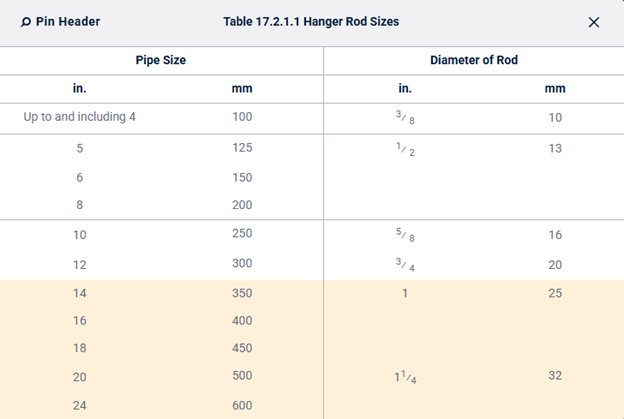
17.2.1.4 U-Hooks
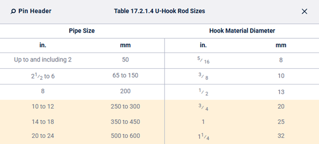
17.2.1.5 Eye Rods
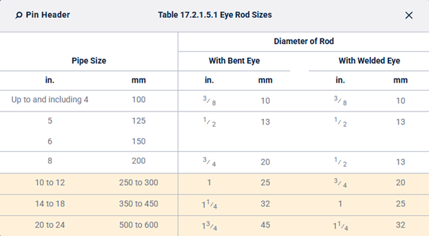
17.2.4 Fasteners in Wood.
Table 17.2.4.2.1 Screw Dimensions for Ceiling Flanges and U-Hooks
Remains similar but adds more options to the U-Hooks allowance of pipe size up to and including 2 inch.
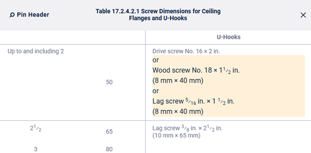
17.3 Trapeze Hangers
17.3.2 (New in 2025): “Interpolation of the section modulus values in Table 17.3.1(a) and Table 17.3.1(b) shall not be permitted.”
17.5 Pipe Standards
17.5.4 Pipe Stand Base.
17.5.4.4:
- 2022: “A minimum of four anchors shall be used to attach the base plate to the floor.”
- 2025: “A minimum of four anchors shall be used to attach the base plate to the floor, unless the requirements of 17.5.4.4.1 are met.”
Chapter 18 – Installation Requirements for Seismic Protection
18.2 Flexible Couplings
18.2.2 (New in 2025):
- “A listed flexible coupling or fitting used for seismic protection shall allow axial displacement, rotation, and at least 1 degree of angular movement of the pipe without inducing harm on the pipe. For pipe diameters of 8 in. (200 mm) and larger, the angular movement is permitted to be less than 1 degree but not less than 0.5 degree.”
18.6 Restraint of Branch Lines
18.6.7
- 2022: “Drops and armovers shall not require restraint.”
- 2025: “Drops, armovers, and flexible sprinkler hose fittings shall not require restraint.”
Chapter 19 – Design Approaches
19.1 General
19.1.6 Hose Allowance.
19.1.6.4
- 2022: “For partially sprinklered buildings, the sprinkler demand, not including hose stream allowance, as indicated in Figure 19.2.3.1.1 shall be added to the requirements given in NFPA 14.”
- 2025: “For partially sprinklered buildings, the sprinkler demand, not including hose stream allowance, as indicated in Chapters 19 through 28 shall be added to the requirements given in NFPA 14.”
19.2 Occupancy Hazard Fire Control Approach for Spray Sprinklers
19.2.2 Water Demand Requirements – Pipe Schedule Method.
19.2.2.3
-
2022 permitted pipe schedule for:
- Additions/modifications to existing pipe schedule systems
- Additions/modifications to existing extra hazard pipe schedule systems
- New systems ≤ 5000 ft²
- New systems > 5000 ft² @ 50 psi at highest sprinkler
- 2025 permits pipe schedule ONLY for:
- New systems ≤ 5000 ft²
- New systems > 5000 ft² @ 50 psi
19.2.3 Water Demand Requirements – Hydraulic Calculation Methods.
19.2.3.1 General
19.2.3.1.1
-
2022 allowed:
- Single-point density/area (new systems)
- Density/area curves (existing systems)
- Room design method
- Special design areas
- 2025 allows ONLY:
- Single-point density/area (Table 19.2.3.1.1)
- Room design method
- Special design areas
19.2.3.1.5 Unsprinklered Combustible Concealed Spaces.
19.2.3.1.5.2 “The following unsprinklered concealed spaces shall not require a minimum area of sprinkler operation of 3000 ft2 (280 m2):”
- 2022:
- (5) Concealed spaces where rigid materials are used and the exposed surfaces comply with one of the following in the form in which they are installed in the space:
- (a) The surface materials have a flame spread index of 25 or less and the materials have been demonstrated to not propagate fire more than 10.5 ft (3.2 m) when tested in accordance with ASTM E84, Standard Test Method for Surface Burning Characteristics of Building Materials, or UL 723, Standard for Test for Surface Burning Characteristics of Building Materials, extended for an additional 20 minutes in the form in which they are installed in the space
- (8) Vertical pipe chases under 10 ft2 (0.9 m2), provided that in multifloor buildings the chases are firestopped at each floor using materials equivalent to the floor construction and pipe penetrations at each floor are properly sealed, and where such pipe chases contain no sources of ignition, and piping is noncombustible
- (10) Light or ordinary hazard occupancies where noncombustible or limited-combustible ceilings are attached to the bottom of composite wood joists either directly or on to metal channels not exceeding 1 in. (25 mm) in depth, provided the adjacent joist channels are firestopped into volumes not exceeding 160 ft3 (4.5 m3) using materials equivalent to 1⁄2 in. (13 mm) gypsum board, and at least 31⁄2 in. (90 mm) of batt insulation is installed at the bottom of the joist channels when the ceiling is attached utilizing metal channels
- Annex: The gypsum board (or equivalent material) used as the firestopping will compartment the concealed space and restrict the ability for fire to spread beyond 160 ft3 (4.5 m3) zones covering multiple joist channels.
- (5) Concealed spaces where rigid materials are used and the exposed surfaces comply with one of the following in the form in which they are installed in the space:
- 2025:
- (5) Concealed spaces where rigid materials are used and the exposed surfaces comply with one of the following in the form in which they are installed in the space:
- (a) The surface materials have a flame spread index of 25 or less and the materials have demonstrated that the flame front does not progress more than 10.5 ft (3.2 m) beyond the centerline of the burners at any time during the 30-minute test period, when tested in accordance with ASTM E84, Standard Test Method for Surface Burning Characteristics of Building Materials, or UL 723, Test for Surface Burning Characteristics of Building Materials, extended for an additional 20 minutes in the form in which they are installed in the space.
- (8) Vertical pipe chases under 10 ft2 (0.9 m2), provided that in multifloor buildings the chases are constructed with blocking at each floor and pipe penetrations at each floor are properly sealed, and where such pipe chases contain no sources of ignition, and piping is noncombustible
- (10) Light or ordinary hazard occupancies where noncombustible or limited-combustible ceilings are attached to the bottom of composite wood joists either directly or on to metal channels not exceeding 1 in. (25 mm) in depth, provided the adjacent joist channels are constructed with blocking so that volumes not exceeding 160 ft3 (4.5 m3) using materials equivalent to 1⁄2 in. (13 mm) gypsum board, and at least 31⁄2 in. (90 mm) of batt insulation is installed at the bottom of the joist channels when the ceiling is attached utilizing metal channels
- Annex: The gypsum board (or equivalent material) used as the blocking material will compartment the concealed space and restrict the ability for fire to spread beyond 160 ft3 (4.5 m3) zones covering multiple joist channels.
- (5) Concealed spaces where rigid materials are used and the exposed surfaces comply with one of the following in the form in which they are installed in the space:
19.2.3.2 Density/Area Method.
19.2.3.2.1 Water Supply.
- 19.2.3.2.1.1
- 2022: “The water supply requirement for sprinklers only shall be calculated from Table 19.2.3.1.1 for new systems and from the density/area curves of Figure 19.2.3.1.1 for the evaluation or modification of existing systems, or from Chapter 27where density/area criteria are specified for special occupancy hazards.”
- 2025: “The water supply requirement for sprinklers only shall be calculated from Table 19.2.3.1.1 or from Chapter 27 where density/area criteria are specified for special occupancy hazards.”
- 19.2.3.2.1.2 (Deleted in 2025)
- When using Figure 19.2.3.1.1, the calculations shall satisfy any single point on the appropriate density/area curve.
- 19.2.3.2.1.3 (Deleted in 2025)
- When using Figure 19.2.3.1.1, it shall not be necessary to meet all points on the selected curves.
19.2.3.2.4 Sloped Ceilings.
- 2022:
- The system area of operation shall be increased by 30 percent without revising the density when the following types of sprinklers are used on sloped ceilings with a pitch exceeding 1 in 6 (a rise of 2 units in a run of 12 units, a roof slope of 16.7 percent) in nonstorage applications:
- Spray sprinklers, including extended coverage sprinklers listed in accordance with 11.2.1(4), and quick-response sprinklers
- CMSA sprinklers
- The system area of operation shall be increased by 30 percent without revising the density when the following types of sprinklers are used on sloped ceilings with a pitch exceeding 1 in 6 (a rise of 2 units in a run of 12 units, a roof slope of 16.7 percent) in nonstorage applications:
- 2025:
- Where spray sprinklers, including extended-coverage and quick-response sprinklers, are installed under a ceiling/roof deck with a slope that exceeds 2 in 12, one of the following requirements shall be implemented:
- A horizontal false ceiling capable of withstanding an uplift force of 3 lb/ft2 (14.6 kg/m2) is installed below the sloped ceiling and supplemented with ceiling sprinklers.30% increase (unobstructed)
- The design area for the ceiling sprinkler system is increased by 30 percent for unobstructed construction.Mandatory sprinkler-in-channel layouts
- Where the ceiling slope does not exceed 4 in 12, apply the sprinkler system criteria specified in Chapter 19 when all of the following conditions are met:
- Purlins or beams supporting the roof deck run across the roof slope.
- Purlins or beams do not exceed 18 in. (450 mm) deep.
- Purlins or beams do not exceed 5 ft (1.5.m) on center.
- Bays created by the solid structural members are not more than 40 ft (12 m) on center.
- Purlin or beam channels are provided with blocking above each solid structural member.
- For obstructed construction where the ceiling slope does not exceed 4 in 12, install sprinklers in every channel.
- For obstructed construction that does not meet (3) or (4), the design area for the ceiling sprinkler system is increased by 30 percent.
- Where spray sprinklers, including extended-coverage and quick-response sprinklers, are installed under a ceiling/roof deck with a slope that exceeds 2 in 12, one of the following requirements shall be implemented:
19.2.3.2.5 Sprinklers for Ceiling Heights Over 30 ft (9.1 m). (New in 2025)
“Where sprinklers are installed in areas with ceiling heights greater than 30 ft (9.1 m) above the finished floor, the requirements of Section 19.2 shall apply except as modified by 19.2.3.2.5 and Table 19.2.3.2.5.”
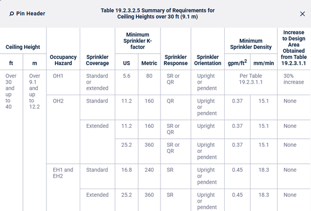
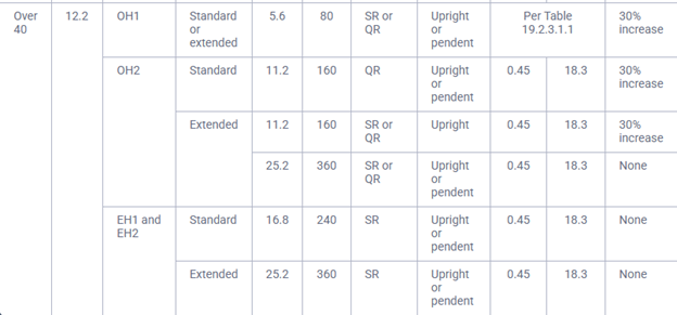
19.2.3.2.5.1 General Sprinkler Characteristics for Ceiling Heights over 30 ft (9.1 m).
(A)
- Sidewall sprinklers shall not be permitted for use in Ordinary Hazard Group 1 and higher occupancy hazards where the ceiling height is greater than 30 ft (9.1 m). [See 10.3.2(3).]
- Annex: The results of Test Nos. 1 and 2 listed in Table C.27 demonstrate that standard-response K-5.6 (K-80) and K-8.0 (K-115) sprinklers can provide fire control for a simulated Ordinary Hazard Group 1 storage array under a 58 ft (17.7 m) high ceiling using a 0.15 gpm/ft2 (6.1 mm/min) density. However, the number of sprinklers that operated resulted in a design area larger than that specified in Table 19.2.3.1.1 coupled with significant sprinkler skipping for both tests. As a result, the design areas in Table 19.2.3.1.1 are being increased, while maintaining the same design density, to account for the test results.
(B)
- Sprinklers having a nominal K-factor less than K-11.2 (K-160) shall not be permitted for use in Ordinary Hazard Group 2 and higher occupancy hazards where the ceiling height is greater than 30 ft (9.1 m). (See 9.4.5.)
- Annex: The results of a test reported in the 2014 Suppression Detection conference proceedings (available from the NFPA Library) demonstrated that standard-response K-8.0 (K-115) sprinklers can provide fire control for a simulated Ordinary Hazard Group 2 storage array under a 40 ft (12.2 m) high ceiling using a 0.37 gpm/ft2 (15 mm/min) density. However, with 12 sprinklers operating during this test, it demonstrated that a density of 0.37 gpm/ft2 (15 mm/min) is more applicable than the density of 0.20 gpm/ft2 (8.1 mm/min) that is provided in Table 19.2.3.1.1 and therefore has been given as the design density for this ceiling height. In addition, the results from Test Nos. 6 and 7 in Table C.27 along with a test reported in the 2014 Suppression Detection conference proceedings (available from the NFPA Library) suggest that the use of a K-11.2 (K-160) sprinkler will provide better fire control, as suggested by the requirements given in 21.1.4, even though this is not a storage occupancy.
(C)
- Extended-coverage pendent sprinklers having a nominal K-factor of K-22.4 (K-320) or less shall not be permitted for use in Ordinary Hazard Group 2 and higher occupancy hazards where the ceiling height is greater than 30 ft (9.1 m). (See 11.2.1.1.)
- Annex: The results of Test Nos. 6 and 7 listed in Table C.27 demonstrated that quick-response K-11.2 (K-160) sprinklers can provide fire control for a simulated Ordinary Hazard Group 2 storage array under a 60 ft (18.3 m) high ceiling using a 0.45 gpm/ft2 (18.3 mm/min) density. However, with 13 and 16 sprinklers operating during these two tests, it demonstrated that a density of 0.45 gpm/ft2 (18.3 mm/min) is more applicable than the density of 0.20 gpm/ft2 (8.1 mm/min) that is provided in Table 19.2.3.1.1 coupled with a design area greater than the 1500 ft2 (140 m2) given in Table 19.2.3.1.1. As a result, the original design density of 0.20 gpm/ft2 (8.1 mm/min) has been increased to 0.45 gpm/ft2 (18.3 mm/min), and the design area of 1500 ft2 (140 m2) has been increased by 30 percent. The 30 percent increase to the design area, however, was not applied to the K-25.2 (K-360) extended-coverage sprinkler due to the very positive results (only one sprinkler operated) obtained with it during Test 8 listed in Table C.27.
(D)
- Standard-response standard-coverage sprinklers shall not be permitted for use in Ordinary Hazard Group 2 occupancies where the ceiling height is greater than 30 ft (9.1 m). (See 10.2.5.)
- Annex: The large-scale fire testing applicable to the requirements of this section demonstrated that for standard-coverage sprinklers, the use of quick-response sprinklers provided an acceptable level of fire control for simulated Ordinary Hazard Group 2 occupancy hazards. As a result, quick-response standard-coverage sprinklers with K-factors of K-11.2 (K-160) or greater are required for the protection of Ordinary Hazard Group 2 occupancy hazards where the ceiling height exceeds 30 ft (9.1 m).
19.2.3.2.5.2 Sprinkler Density/Areas for Ceiling Heights Over 30 ft (9.1 m).
(A)
- For Ordinary Hazard Group 1 occupancies where the ceiling height is greater than 30 ft (9.1 m), the design areas obtained from Table 19.2.3.1.1 shall be increased by 30 percent.
- Annex: The results of Test Nos. 1 and 2 listed in Table C.27 demonstrate that standard-response K-5.6 (K-80) and K-8.0 (K-115) sprinklers can provide fire control for a simulated Ordinary Hazard Group 1 storage array under a 58 ft (17.7 m) high ceiling using a 0.15 gpm/ft2 (6.1 mm/min) density. However, the number of sprinklers that operated resulted in a design area larger than that specified in Table 19.2.3.1.1 coupled with significant sprinkler skipping for both tests. As a result, the design areas in Table 19.2.3.1.1 are being increased, while maintaining the same design density, to account for the test results.
(B)
- For Ordinary Hazard Group 2 occupancies where the ceiling height is greater than 30 ft (9.1 m) but does not exceed 40 ft (12.2 m), the ceiling sprinkler system shall use a minimum density of 0.37 gpm/ft2 (15.1 mm/min) in combination with the design area obtained from Table 19.2.3.1.1.
- Annex: The results of a test reported in the 2014 Suppression Detection conference proceedings (available from the NFPA Library) demonstrated that standard-response K-8.0 (K-115) sprinklers can provide fire control for a simulated Ordinary Hazard Group 2 storage array under a 40 ft (12.2 m) high ceiling using a 0.37 gpm/ft2 (15 mm/min) density. However, with 12 sprinklers operating during this test, it demonstrated that a density of 0.37 gpm/ft2 (15 mm/min) is more applicable than the density of 0.20 gpm/ft2 (8.1 mm/min) that is provided in Table 19.2.3.1.1 and therefore has been given as the design density for this ceiling height. In addition, the results from Test Nos. 6 and 7 in Table C.27 along with a test reported in the 2014 Suppression Detection conference proceedings (available from the NFPA Library) suggest that the use of a K-11.2 (K-160) sprinkler will provide better fire control, as suggested by the requirements given in 21.1.4, even though this is not a storage occupancy.
(C)
- For Ordinary Hazard Group 2 occupancies where the ceiling height is greater than 40 ft (12.2 m), the ceiling sprinkler system shall comply with the following:
- Use a minimum density of 0.45 gpm/ft2 (18.3 mm/min)
- Increase the design areas obtained from Table 19.2.3.1.1 by 30 percent
- Use the design areas from Table 19.2.3.1.1, without a 30 percent increase, where an extended-coverage sprinkler having a minimum nominal K-factor of K-25.2 (K-360) is used
- Annex: The results of Test Nos. 6 and 7 listed in Table C.27 demonstrated that quick-response K-11.2 (K-160) sprinklers can provide fire control for a simulated Ordinary Hazard Group 2 storage array under a 60 ft (18.3 m) high ceiling using a 0.45 gpm/ft2 (18.3 mm/min) density. However, with 13 and 16 sprinklers operating during these two tests, it demonstrated that a density of 0.45 gpm/ft2 (18.3 mm/min) is more applicable than the density of 0.20 gpm/ft2 (8.1 mm/min) that is provided in Table 19.2.3.1.1 coupled with a design area greater than the 1500 ft2 (140 m2) given in Table 19.2.3.1.1. As a result, the original design density of 0.20 gpm/ft2 (8.1 mm/min) has been increased to 0.45 gpm/ft2 (18.3 mm/min), and the design area of 1500 ft2 (140 m2) has been increased by 30 percent. The 30 percent increase to the design area, however, was not applied to the K-25.2 (K-360) extended-coverage sprinkler due to the very positive results (only one sprinkler operated) obtained with it during Test 8 listed in Table C.27.
(D)
- For Extra Hazard Groups 1 and 2 occupancies where the ceiling height is greater than 30 ft (9.1 m), the ceiling sprinkler system shall use a minimum density of 0.45 gpm/ft2 (18.3 mm/min) in combination with the design areas obtained from Table 19.2.3.1.1.
- Annex: The test data listed in Table C.27 does not include any tests representing simulated occupancy hazards for either Extra Hazard Group 1 or Extra Hazard Group 2. However, based on the results from the test data listed in Table C.27, the minimum design density requirements of 0.30 gpm/ft2 (12.2 mm/min) for Extra Hazard Group 1 and 0.40 gpm/ft2 (16.3 mm/min) for Extra Hazard Group 2 are both now less than the 0.45 gpm/ft2 (18.3 mm/min) design density required for Ordinary Hazard Group 2. Therefore, the minimum design density for both Extra Hazard Group 1 and Extra Hazard Group 2 has been increased to 0.45 gpm/ft2 (18.3 mm/min) while maintaining the same required design area.
19.2.3.2.7 Extra Hazard Occupancies.
- 19.2.3.2.7.1
- For extra hazard occupancies with ceilings not exceeding 30 ft (9.1 m) in height, the system area of sprinkler operation shall be permitted to be reduced by 25 percent without revising the density, but not to less than 2000 ft2 (185 m2) where one of the following conditions occurs:
- High-temperature sprinklers are used.
- K-11.2 (160) or larger sprinklers are used.
- For extra hazard occupancies with ceilings not exceeding 30 ft (9.1 m) in height, the system area of sprinkler operation shall be permitted to be reduced by 25 percent without revising the density, but not to less than 2000 ft2 (185 m2) where one of the following conditions occurs:
- 19.2.3.2.7.2
- The 25 percent reduction permitted by 19.2.3.2.7.1 shall only be permitted to be applied once.
19.3 Special Design Approaches
19.3.1 Residential Sprinklers
19.3.1.3
- 2022: “Unless the requirements of 19.3.1.4 are met, the minimum required discharge…”
- 2025: “The minimum required discharge…”
- In 2022, 19.3.1.4 was an explicit exception allowing listed discharge criteria <0.1 gpm/ft² for modifications/additions to existing residential systems.
19.3.1.4 (Deleted in 2025)
For modifications or additions to existing systems equipped with residential sprinklers, the listed discharge criteria less than 0.1 gpm/ft2 (4.1 mm/min) shall be permitted to be used.
19.3.1.4.1 (Deleted in 2025)
Where replacing residential sprinklers manufactured prior to 2003 that are no longer available from the manufacturer and that are installed using a design density less than 0.05 gpm/ft2 (2.0 mm/min), a residential sprinkler with an equivalent K-factor (± 5 percent) shall be permitted to be used provided the currently listed coverage area for the replacement sprinkler is not exceeded.
19.5 Design Approaches for Supplemental Sprinklers (New in 2025)
When required to be included in the hydraulic calculations in accordance with 28.2.4.7.4.3, the design approach for supplemental sprinklers shall be permitted to be based on the hazard located directly below the obstruction.
Chapter 20 – General Requirements for Storage
20.1 General
Annex added in 2025:
2025 adds an entirely new A.20.1 annex section providing extensive guidance on what information should be documented when sprinklers are tested at a laboratory for determining discharge criteria. This is a substantive new addition covering 19 line items of test documentation requirements plus recommendations for proposing installation limits. This annex did not exist in 2022.
When sprinklers are being tested at a laboratory for the purposes of determining sprinkler discharge criteria for a specific hazard, the entity sponsoring the testing should request that the laboratory provide them with a report or test data that documents how the tests were conducted and what the results of the tests were, but not include proprietary product design information about the sprinkler. The following information should be included for each test in the report or data package:
- Material(s) being used as the fuel for the fire.
- Dimensional details of test commodity and storage arrangement.
- Nominal height of the stored commodity above the floor.
- Nominal clearance between the top of storage and the ceiling.
- Sprinkler identification number (SIN).
- K-factor of the sprinkler.
- Temperature rating and response characteristics of the sprinkler.
- Distance of the sprinkler deflector (or thermal element) below the ceiling.
- Orientation of the sprinkler (upright, pendent, horizontal).
- Obstructions to sprinklers (if any) including the branch line piping for upright sprinklers.
- Water pressure at sprinkler or flow from sprinkler during test.
- Sprinkler spacing.
- Fire location with respect to upright and pendent sprinkler(s). Typical test locations might include the following (note that tests are not required in all locations):
- Under one sprinkler
- Between two sprinklers on the same branch line
- Between four sprinklers
- At a dry spot in the sprinkler’s spray pattern as identified in flow testing
- Fire location with respect to sidewall sprinkler(s). Test locations that should be considered include the following (note that tests are not required in all locations):
- At the most remote location from a single sprinkler
- Centered between two sprinklers at the far point of the coverage area
- Centered between four sprinklers when sprinklers are on opposite walls spraying into a room or space
- Directly underneath and behind a single sprinkler
- On the same wall as the sprinklers, centered between two sprinklers
- At a dry spot in the sprinkler’s spray pattern as identified in flow testing
- Fire test results. The following are examples of successful criteria:
- The fire does not show evidence of sustained combustion at the far ends of the main test array.
- The fuel is not completely consumed.
- The fire does not show evidence of sustained combustion at the outer edges of the target arrays.
- The average one-minute temperature of a simulated steel structural member installed near the ceiling above ignition does not exceed 1000°F (538°C), or the ceiling temperatures are controlled so that they are below a predetermined limit.
- Sprinklers do not operate at the edge of the protection array.
- Number of sprinklers that open during the test, where they were in relation to the fire, and what time they opened after ignition.
- Gas temperatures above ignition and near each installed sprinkler.
- Description of area or commodity damaged by fire.
- Other test conditions or parameters or observations that would help support a decision or limitation on the use of the sprinkler based on this test program.
The entity sponsoring the tests is responsible for proposing appropriate limits to the installation requirements and hazards that their sprinkler can protect based on the parameters of the fire tests and the results of those tests. This recommendation needs to include the following:
- The number of sprinklers that would be appropriate for the design area.
- The minimum discharge (pressure or flow) necessary from each sprinkler.
- The number of sprinklers that operated in the worst-case fire test with an appropriate safety factor applied (typically 1.5) to that number to account for variables not considered during the test program.
- An appropriate minimum number of sprinklers can be applied, depending on the hazard being protected.
20.4 Commodity Classes
20.4.1 Class I
Table A.20.4.1 (Class I Examples)
- 2022 listed “Appliances; major; no appreciable plastic trim; cartoned” as Class I.
- 2025 corrects to “exposed”, aligning with Table A.20.4(b), which has always shown the exposed version as Class I and cartoned as Class II.
Table A.20.4.3 (Class III Examples)
- 2022 included “Fabric; synthetic (except rayon and nylon); up to 50/50 blend” and “Thread or yarn; synthetic (except rayon and nylon); up to 50/50 blend; wood or paper spools” as Class III examples.
- 2025 removes both, consistent with Table A.20.4(b) listing these as Group A Nonexpanded.
20.4.8.1 Group B / Free-Flowing Group A Plastics
- 2022: “Group B plastics and free-flowing Group A plastics shall be protected the same as Class IV commodities.”
- 2025: “Unless the requirements of 20.4.3 are met, Group B plastics or free-flowing Group A plastics shall be protected the same as Class IV commodities.”
20.4.12 Baled Cotton (2022 Renumbered 20.4.11.1).
20.4.13 Plastic Motor Vehicle Components (2022 Renumbered 20.7 & 20.5.4).
20.5 Equivalent Storage Arrangement
Section title changed:
- 2022: “Storage Arrangement”
- 2025: “Equivalent Storage Arrangement”
20.5.3.3 Aisles and 20.5.3.4 Flues with all subsections (Deleted)
20.5.4 Plastic Motor Vehicle Components (Deleted)
20.6 Aisle and Flue Space Requirements for Storage. (New Section in 2025)
New standalone Section 20.6
20.6.2.1.2 (2022 origin 20.5.3.4.1.2)
- 2022: “For Class I through IV and Group A plastic nominal 6 in. (150 mm) longitudinal flue spaces shall be provided in double-row racks for storage over 25 ft (7.6 m).”
- 2025: “For Class I through Class IV and Group A plastic commodities in double-row open racks, a nominal 6 in. (150 mm) longitudinal flue space shall be provided for storage over 25 ft (7.6 m).” Adds “in double-row open racks” and “commodities” for clarity.
20.6.2.1.3 (New in 2025)
- 2025 adds a new subsection explicitly stating that:
- “For Class I through Class IV and Group A plastic commodities in multiple-row open racks, longitudinal flue spaces shall not be required when all of the following are met:
- Minimum nominal 6 in. (150 mm) wide transverse flue spaces are provided on maximum 5 ft (1.5 m) intervals.
- The rack depth does not exceed 20 ft (6.1 m).
- The minimum aisle width is 3.5 ft (1.1 m).”
20.7 Protection Criteria for Roll Paper Storage.
20.7 Plastic Motor Vehicle Components (2022 Deleted as Standalone Section):
20.9 Building Construction and Storage: Heights and Clearance.
20.9.1 Ceiling Slope
Section title changed:
- 2022: “Ceiling Slope”
- 2025: “Sloped Ceilings”
Scope expanded:
- 2022: Criteria apply to “Chapters 20 through 25.”
- 2025: Criteria apply to “Chapters 20 through 26.” Chapter 26 is now explicitly included.
20.9.1.1 Protection Options
- 2025 adds Annex A.20.9.1.1: “The intent is to have a structural member that prevents the passage of heat. The member can have holes for penetrations with reasonable clearance and penetration sealant is not expected.”
- 2022 had only 2 options for storage under ceilings exceeding 2 in 12: (1) where a specific section in Chapters 20–25 permits it, or (2) in-rack sprinklers per Section 25.6 with no storage above.
- 2025 expands to 6 options, based on FPRF research:
- In-rack sprinklers per Section 25.7 with no storage above highest in-rack level.
- Install a horizontal false ceiling capable of withstanding 3 lb/ft² uplift, with ceiling sprinklers below.
- Protect per guidance in Chapters 20–26 that specifically permits slopes exceeding 2 in 12.
- For obstructed construction with slope ≤ 4 in 12 using CMDA: install sprinklers in every channel.
- For unobstructed construction with slope ≤ 4 in 12: increase design area by 50%.
- For obstructed construction with slope ≤ 4 in 12: use standard criteria if purlins/beams run across the slope, are ≤ 18 in. deep, ≤ 5 ft on center, bays ≤ 40 ft on center, and channels are blocked above each solid structural member.
Storage Height
- 20.9.3.2 (New in 2025): “The storage height shall be measured from the floor level to the top of the commodity.”
20.9.4 Clearance to Ceiling
- 20.9.4.2 through 20.9.4.5 Relocated from Chapter 20 into Chapter 21 as 21.1.9 through 21.1.9.3.
20.9.5 Roof Vents and Draft Curtains
- A.20.9.5.1 expanded:
- 2022: “Sprinkler protection criteria are based on the assumption that roof vents and draft curtains are not being used.”
- 2025: “…and could be detrimental to the performance of the sprinkler system. If manual roof vents are provided, care should be taken to not open the manual roof vents before the fire has been controlled or suppressed.” Substantive operational guidance added.
- 20.9.5.1 rewritten:
- 2022: “Manually operated roof vents or automatic roof vents with operating elements that have a higher temperature classification than the automatic sprinklers shall be permitted.”
- 2025: “Automatic roof vents shall not be required in areas protected by automatic sprinkler systems.”
20.9.5.2 rewritten:
- 2022: “ESFR sprinklers shall not be used in buildings with automatic heat or smoke vents unless the vents use a high-temperature rated, standard-response operating mechanism.”
- 2025: “Where automatic roof vents are provided, the automatic roof vents shall have a higher temperature rating and a higher RTI than the automatic sprinklers.”
20.10 Unsprinklered Combustible Concealed Spaces
20.10.2 (4) rewritten:
- 2022: A single condition, flame spread index ≤ 25 and materials not propagating fire more than 10.5 ft when tested per ASTM E84 or UL 723 extended 20 minutes.
- 2025: Splits this into two alternatives (a) and (b):
- Same as 2022, but with updated wording (“flame front does not progress more than 10.5 ft beyond the centerline of the burners at any time during the 30-minute test period”).
- New alternative: Materials may instead comply with ASTM E2768, Standard Test Method for Extended Duration Surface Burning Characteristics (30 min Tunnel Test). This new standard is recognized as an equivalent compliance path.
20.10.2 (7) rewritten:
- 2022: Vertical pipe chases required to be “firestopped at each floor using materials equivalent to the floor construction.”
- 2025: Requires chases to be “constructed with blocking at each floor.” The firestopping language is replaced with the simpler “blocking” requirement — a meaningful change in the construction standard applied.
20.16 Discharge Considerations: General.
20.16.4 Design Approaches for Supplemental Sprinklers (New in 2025)
“When required to be included in the hydraulic calculations in accordance with 28.2.4.7.4.3, the design approach for supplemental sprinklers shall be permitted to be based on the hazard located directly below the obstruction utilizing the bottom plane of the obstruction as the ceiling level.”
20.17 Protection of Idle Pallets
20.17.1 Wood Pallets
- 20.17.1.4 (New in 2025): “Idle wood pallets shall be permitted to be stored in racks when protected in accordance with Section 25.7 using the criteria for exposed expanded plastic commodity hazard.”
20.17.3 Idle Pallets Stored on Racks, on Shelves, and Above Doors
- 20.17.3.4 (New in 2025): “Idle pallets shall be permitted to be stored in racks when protected in accordance with Section 25.7 using criteria for exposed nonexpanded plastic commodity hazard.”
20.19 Protection of Racks with Solid Shelves\
- 2022: Section 20.19 contained a full set of detailed normative requirements including 20.19.1 General, 20.19.2 Open Racks Combined with In-Rack Sprinklers, 20.19.3.1–20.19.3.5 (vertical spacing of in-rack sprinklers), and 20.19.4.1–20.19.4.3 (horizontal spacing of in-rack sprinklers) — 10+ normative subsections with detailed criteria.
- 2025: The section is drastically shortened and replaces all of this with just two subsections:
- 20.19.1: “Racks containing solid shelves shall comply with Section 25.3.”
- 20.19.2: “Solid shelving requirements shall not apply to a noncombustible product stored with noncombustible storage aids, including pallets, straps, containers, and shelving material.”
Chapter 21 – Protection of High-Piled Storage Using Control Mode Density Area (CMDA) Sprinklers
The 2025 edition has consistently eliminated the new/existing system distinction throughout Chapter 21. The old density/area design curves (for existing systems) have been removed from Sections 21.2, 21.4.1.2, 21.4.1.3, 21.4.1.4, and 21.4.1.7. Only the single-point density tables (introduced in 2022 for new systems) remain, now applying universally.
21.1 General
21.1.5 (Removed in 2025): “Unless the requirements of 21.1.6 are met, the requirements of Table 21.5.1.1 shall not apply to modifications to existing storage application systems, using sprinklers with K-factors of K-8.0 (115) or less.”
21.1.6 (Removed in 2025): “Where applying the requirements of Table 21.5.1.1 utilizing the design criteria of 0.6 gpm/ft2 per 2000 ft2 (24.5 mm/min per 185 m2) to existing storage applications, the requirements of 21.1.4 shall apply.”
21.1.8 Discharge Considerations (Renumbered from 2022 21.1.10)
- 21.1.8.2 (Removed in 2025, formerly 21.1.10.2): “The calculations shall satisfy any single point on appropriate density/area curves for the evaluation or modification of existing systems.”
21.1.9 (Renumbered, 2022 Origin 20.9.4.2). Table slightly modified and renumbered accordingly.
- 21.1.9.1 (Renumbered, 2022 Origin 20.9.4.3). Table slightly modified and renumbered accordingly.
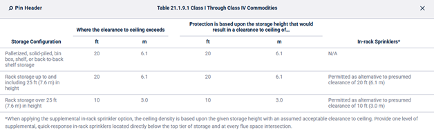
- 21.1.9.2 (Renumbered, 2022 Origin 20.9.4.4). Table slightly modified and renumbered accordingly.
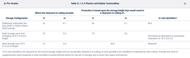
- 21.1.9.3 (Renumbered, 2022 Origin 20.9.4.5)
21.2 Control Mode Density/Area Sprinkler Protection Criteria for Palletized, Solid-Piled, Bin Box, Shelf, or Back-to-Back Shelf Storage of Class I Through Class IV Commodities.
21.2.2 Protection Criteria for Palletized, Solid-Piled, Bin Box, Shelf, or Back-to-Back Shelf Storage of Class I Through Class IV Commodities Stored Over 12 ft (3.7 m) in Height.
- “New vs. existing” system distinction removed.
- Table is identical
- 2022 had a two-tier structure:
- 21.2.2.1 General with 21.2.2.1.1 (new systems use Table 21.2.2.2.1) and 21.2.2.1.2 (existing systems may use density/area curves).
- 21.2.2.2 New System Criteria (21.2.2.2.1 table, 21.2.2.2.2 back-to-back shelf).
- 21.2.2.3 Evaluation or Modification of Existing Systems (21.2.2.3.1 through 21.2.2.3.7, including Figures 21.2.2.3.1, 21.2.2.3.2, 21.2.2.3.3, and all associated commentary and ASK THE AHJ blocks).
- 2025 eliminates the new/existing distinction entirely and replaces it with:
- 21.2.2.1 System Criteria: a single subsection with one table and one back-to-back shelf rule.
- 21.2.2.1.1 Densities from Table 21.2.2.1.1 (same values as 2022’s Table 21.2.2.2.1, renumbered).
- 21.2.2.1.2 Back-to-back shelf rule (same as 2022’s 21.2.2.2.2, renumbered).
- All 21.2.2.3 (existing system density/area curves) is removed from 2025, including Figures 21.2.2.3.1, 21.2.2.3.2, 21.2.2.3.3, and subsections 21.2.2.3.1 through 21.2.2.3.7. This is a significant simplification; the density/area curves for existing systems are no longer included in this section of the 2025 text.
21.4 Control Mode Density/Area Sprinkler Protection Criteria for Rack Storage of Class I Through Class IV Commodities.
21.4.1 Protection Criteria for Rack Storage of Class I Through Class IV Commodities Stored Over 12 ft (3.7 m) Up to and Including 25 ft (7.6 m) in Height.
21.4.1.1 General
New/existing system distinction removed:
- 2022 had two subsections: 21.4.1.1.1 (new systems use tables) and 21.4.1.1.2 (existing systems may use density/area curves).
- 2025 collapses to a single 21.4.1.1 with unified direction, eliminating the split. Same substance as the new system path only.
21.4.1.2 Single- and Double-Row Racks
New/existing system distinction removed (substantive):
- 2022 had two tiers: 21.4.1.2.1 (New System Criteria with Tables 21.4.1.2.1.1(a)–(e)) and 21.4.1.2.2 (Evaluation/Modification of Existing Systems with Figures 21.4.1.2.2.1(a)–(e) and Table 21.4.1.2.2.1).
- 21.4.1.2.2 Evaluation or Modification of Existing Systems for Single- or Double-Row Rack Storage of Class I Through Class IV Commodities Stored Over 12 ft (3.7 m) Up to and Including 25 ft (7.6 m) in Height. (Deleted in 2025)
- Figures 21.4.1.2.2.1(a) through (e) and Table 21.4.1.2.2.1 (which directed users to those figures based on configuration) are entirely absent from 2025.
- 21.4.1.2.2 Evaluation or Modification of Existing Systems for Single- or Double-Row Rack Storage of Class I Through Class IV Commodities Stored Over 12 ft (3.7 m) Up to and Including 25 ft (7.6 m) in Height. (Deleted in 2025)
- 2025 has only one tier. Tables are renumbered 21.4.1.2.1(a) – (e). All density values within the tables are identical to 2022’s new system tables.
21.4.1.3 Protection for Multiple-Row Racks — Rack Depth Up to and Including 16 ft (4.9 m), Aisles 8 ft (2.4 m) or Wider, Storage Height Over 12 ft (3.7 m) Up to and Including 25 ft (7.6 m). (Renumbered 2022’s 21.4.1.5 and 21.4.1.6)
- New/existing system distinction removed.
- 2022 had 21.4.1.3.1 (New System) with Tables 21.4.1.3.1.1(a) – (e) and 21.4.1.3.2 (Existing System) with Table 21.4.1.3.2.1.
- Deleted – Table 21.4.1.3.2.1 (directing existing system users to density/area curves with 1.25× density multiplier) is entirely absent from 2025.
- 2025 has only one tier. Tables are renumbered 21.4.1.3.1(a) – (e). All density values are identical to 2022’s new system tables.
21.4.1.4 Protection for Multiple-Row Racks — Rack Depth Over 16 ft (4.9 m) or Aisles Narrower Than 8 ft (2.4 m), Storage Height Over 12 ft (3.7 m) Up to and Including 25 ft (7.6 m). (Renumbered 2022’s 21.4.1.4 and 21.4.1.5)
- New/existing system distinction removed.
- 2022 had 21.4.1.4.1 (New System) and 21.4.1.5 (Existing System with Table 21.4.1.5.1).
- 2025 combines under 21.4.1.4 with the new system table only. All density values are identical.
- Deleted – Existing system table for multiple-row racks (deep/narrow aisle):
- 2022’s 21.4.1.5 and Table 21.4.1.5.1 (directing existing system users to density/area curves) are entirely absent from 2025.
21.4.1.5 Multiple-Row Racks – Storage Height Over 12 ft (3.7 m) Up to and Including 25 ft (7.6 m). (Renumbered 2022’s 21.4.1.6)
- Table 21.4.1.5.1 (Deleted)
21.4.1.7 Ceiling Sprinkler Density Adjustments restructured:
- 2022’s 21.4.1.7 had two subsections:
- 21.4.1.7.1: For existing systems, adjust densities from design curves using Figure 21.4.1.7.1.
- 21.4.1.7.2: Slave pallet 20% density increase.
- 2025’s 21.4.1.6 Ceiling Sprinkler Density Adjustments.
- Retains only the slave pallet increase (as 21.4.1.6.1).
- 21.4.1.7.1 and Figure 21.4.1.7.1 (Deleted in 2025)
- The existing system density adjustment curve (Figure 21.4.1.7.1 — Evaluation or Modification of Existing System’s Ceiling Sprinkler Density vs. Storage Height) and its normative text are entirely absent from 2025
Chapter 22 – CMSA Requirements for Storage Applications
- Chapter 22’s 2022 and 2025 versions of the NFPA 13 code are identical.
Chapter 23 – ESFR Requirements for Storage Applications
23.2 ESFR Design Criteria
- 23.2.3 (New in 2025): “Where ESFR sprinklers are spaced less than the minimum distances permitted and nonstructural baffles are installed in accordance with 14.2.8.4.2(1) to compensate, the design area shall cover a minimum of 768 ft2 (71 m2).”
23.3 ESFR Sprinklers for Palletized, Solid-Piled, or Rack Storage of Class I Through Class IV and Group A Plastic Commodities.
Table 23.3.1
- Table format changed: 2025 adds an explicit maximum storage height column alongside maximum ceiling/roof height.
- Application is clearer: each ESFR option is now tied to a defined ceiling-height/storage-height c ombination.
- Class I–IV and cartoned nonexpanded Group A plastics: table presentation was reorganized so the allowable storage height is now explicitly shown for each ceiling height.
- Cartoned expanded Group A plastics: 2025 adds major new ESFR ceiling-only options, especially with K-22.4 and K-25.2 sprinklers, and extends protection to higher ceiling/storage combinations than were shown in 2022.
- Exposed nonexpanded Group A plastics: 2025 also adds major new ESFR ceiling-only options, again especially with K-22.4 and K-25.2 sprinklers, including higher ceiling/storage combinations.
- Exposed expanded Group A plastics: 2025 substantially reorganizes and clarifies the available options, explicitly separating the lower-pressure barrier-based options from the higher-pressure closed-array options.
- Important cross-reference change: the 2022 table note referring to Section 27.4 was changed in 2025 to Section 23.4, indicating that the exposed expanded Group A plastic barrier criteria are now more directly integrated into Chapter 23.
- New notes in 2025: the table now better distinguishes between options that are directly test-based and options derived from higher-hazard testing logic.
Chapter 24 – Alternative Sprinkler System Designs for Chapters 20 Through 25
24.1 General
- 2025:
- 24.1 Annex adds: “Nothing in this chapter is intended to limit the development and use of equivalency or new technology applications under the provisions of Section 1.5 or Section 1.7.” Not present in 2022. Clarifies that Chapter 24 does not restrict equivalency pathways.
24.2 Sprinkler Design Criteria for Palletized and Solid-Piled, Storage of Class I Through Class IV and Plastic Commodities.
- Table 24.2.1 now adds footnote: “A minimum clearance of 5 ft (1.5 m) shall be provided from sprinkler deflector to the top of storage.”
24.3 Sprinkler Protection Criteria for Open-Frame Rack Storage of Class I Through Class IV and Plastic Commodities.
24.3.1:
- Table 24.3.1 adds the same footnote: “A minimum clearance of 5 ft (1.5 m) shall be provided from sprinkler deflector to the top of storage.”
24.3.2:
- 2022:
- There were two separate tables:
- Table 24.3.2(a) for K-25.2 upright
- Table 24.3.2(b) for K-25.2 pendent
- There were two separate tables:
- 2025:
- Those were consolidated into a single Table 24.3.2.
Table 24.3.3 new footnote:
- 2025 adds to Table 24.3.3: “For the 12-sprinkler design incorporate a 500 gpm (1900 L/min) hose stream allowance and a 90-minute duration.” This specific hose stream and duration requirement for the 12-sprinkler dry system design (40 ft storage / 45 ft ceiling) was not present in 2022 and is a substantive addition.
Chapter 25 – Protection of Rack Storage Using In-Rack Sprinklers
25.1 General Requirements for Ceiling and In-Rack Sprinklers Protecting Rack Storage.
25.1.1 Scope
25.1.1.1
- 2025 Annex adds after the 8-item checklist: “Fire testing of in-rack sprinkler protection schemes described in Chapter 25 have generally demonstrated improved fire protection compared to the ceiling-only sprinkler protection schemes described in Chapters 21 through 24. Lower ceiling temperatures and a reduced amount of smoke/combustion products developed during the fire control or suppression process has typically been observed during fire testing of these in-rack sprinkler systems. A reduction in the amount of smoke/combustion product generation provides greater visibility for the fire service while achieving final extinguishment.”
25.1.2 Chapter Organization
2022:
- 25.1 contains general requirements for the entire chapter.
- 25.2 contains requirements for the protection of miscellaneous and low-piled rack storage using in-rack sprinklers.
- 25.3 contains requirements for in-rack sprinkler protection in combination with CMDA ceiling-level sprinklers.
- 25.4 contains requirements for in-rack sprinkler protection in combination with CMSA ceiling-level sprinklers.
- 25.5 contains requirements for in-rack sprinkler protection in combination with ESFR ceiling-level sprinklers.
- 25.6 contains requirements for in-rack sprinkler protection independent of ceiling-level sprinklers.
- 25.7 contains requirements for the evaluation or modification of existing protection for miscellaneous and low-piled rack storage using in-rack sprinklers. (Removed in 2025)
- 25.8 contains requirements for the evaluation or modification of existing protection for CMDA ceiling-level sprinkler rack storage protection of Class I through Class IV commodities over 12 ft (3.7 m) and up to and including 25 ft (7.6 m) using in-rack sprinklers. (Removed in 2025)
2025:
- 25.1 contains general requirements for the entire chapter.
- 25.2 contains requirements for the protection of miscellaneous and low-piled rack storage using in-rack sprinklers.
- 25.3 contains requirements for in-rack sprinkler protection with solid shelves.
- 25.4 contains requirements for in-rack sprinkler protection in combination with CMDA ceiling-level sprinklers.
- 25.5 contains requirements for in-rack sprinkler protection in combination with CMSA ceiling-level sprinklers.
- 25.6 contains requirements for in-rack sprinkler protection in combination with ESFR ceiling-level sprinklers.
- 25.7 contains requirements for in-rack sprinkler protection independent of ceiling-level sprinklers.
25.1.7 Horizontal Location of In-Rack Sprinklers.
25.1.7.7
- 2022: “Where rack storage of Class I through Class IV commodities is up to and including 25 ft (7.6 m), in-rack sprinklers shall be permitted to be installed horizontally without regard to rack uprights. (See Section C.17.)”
- 2025: “In-rack sprinklers shall be a minimum 3 in. (75 mm) radially from the side of rack uprights. (See Section C.17.)”
25.1.7.8 & 2022’s 25.1.7.9
- 2022’s 25.1.7.8: “Where rack storage is over 25 ft (7.6 m) in height, in-rack sprinklers shall be a minimum 3 in. (75 mm) radially from the side of rack uprights.”
- 2022’s 25.1.7.9: “Where rack storage is over 25 ft (7.6 m) in height and will be protected by face sprinklers, the face sprinklers shall be located within the rack a minimum 3 in. (75 mm) from rack uprights and no more than 18 in. (450 mm) from the aisle face of storage.”
- 2025’s 25.1.7.8: “Face sprinklers shall be located within the rack a minimum 3 in. (75 mm) from rack uprights and no more than 18 in. (450 mm) from the aisle face of storage.”
25.2 Protection of Miscellaneous and Low-Piled Rack Storage Using In-Rack Sprinklers.
25.2.1 Miscellaneous Rack Storage.
25.2.1.4 Ceiling Sprinkler Design in Combination with In-Rack Sprinklers for Miscellaneous Storage.
- 25.2.1.4.1 & 25.2.2.4.1 (Typo Corrected)
- 2022: “0.20 gpm/ft2 (0.8.2 mm/min)”
- 2025: “0.20 gpm/ft2 (8.2 mm/min)”
- 25.2.1.4.3 (Wording Clarification)
- 2022: “The sprinkler system criteria specified in this chapter for miscellaneous storage shall not be limited to a ceiling slope of 2 in 12 (16.7 percent).”
- 2025: “The sprinkler system criteria specified in this chapter for miscellaneous storage shall be permitted for both horizontal and sloped ceilings.”
25.2.2 Low-Piled Rack Storage.
25.2.2.4 Ceiling Sprinkler Design in Combination with In-Rack Sprinklers for Low-Piled Storage.
- 25.2.2.4.2
- 2022: “The sprinkler system criteria specified in this chapter for low-piled storage shall not be limited to a ceiling slope of 2 in 12 (16.7 percent).”
- 2025: “The sprinkler system criteria specified in this chapter for low-piled storage shall be permitted for both horizontal and sloped ceilings.”
25.3 Protection of Racks with Solid Shelves. (New in 2025)
All flow rates, pressures, shelf area thresholds, vertical spacing dimensions, horizontal spacing dimensions, and extension-beyond-shelf distances are identical to the 2022 source sections. No technical values were changed.
- General requirements + open rack combined with in-rack protection rules (2022 Origin 20.19.1 and 20.19.2)
- Vertical spacing – CMDA sprinklers, solid shelves between 20–64 ft² (2022 Origin 20.19.3.1)
- Vertical spacing – CMDA sprinklers, solid shelves > 64 ft² or shelf spacing > 6 ft (2022 Origin 20.19.3.2)
- Vertical spacing – CMSA sprinklers, in-rack sprinklers required at all tiers below highest solid shelf (2022 Origin 25.4.1.3.1)
- Vertical spacing – ESFR sprinklers, in-rack sprinklers required at all tiers below highest solid shelf (2022 Origin: 25.5.1.3.1)
- Partial solid shelf obstruction requirements (2022 Origin 20.19.3.5)
- Horizontal spacing – Class I–IV commodities (10 ft rule) (2022 Origin 20.19.4.1, also duplicated in 25.4.1.2.1 and 25.5.1.2.1)
- Horizontal spacing – Group A plastics (5 ft rule) (2022 Origin 20.19.4.2, also duplicated in 25.4.1.2.2 and 25.5.1.2.2)
- Extension of in-rack sprinklers beyond solid shelf edge (4 ft rule) (2022 Origin 20.19.4.3, also duplicated in 25.4.1.2.3 and 25.5.1.2.3)
25.4 In-Rack Sprinkler Protection in Combination with CMDA Ceiling-Level Sprinklers.
The changes in this section correspond to metrical conversion corrections.
TABLES 25.3.2.1.2.1(A)(a)–(A)(d) / 25.4.2.1.2.1(A)(a)–(A)(d)
- Area designation corrected:
- 2022: “2000 ft² (186 m²)” in the column header for Tables (A)(a)–(A)(d).
- 2025: “2000 ft² (185 m²)”.
- Minor metric rounding corrections in individual density values:
- Several mm/min equivalents are slightly adjusted for rounding consistency. All gpm/ft² values are identical; only the parenthetical SI equivalents change in a handful of cells. Examples found on the values corresponding to “Ceiling Sprinkler System Design [gpm/ft2/2000 ft2 (mm/min/185 m2)]”, below both “High-Temperature-Rated Sprinklers” and “Ordinary- or Intermediate-Temperature-Rated Sprinklers”:
- 0.17 (7.0), 0.17 (6.9)
- 0.18 (7.4), 0.18 (7.3)
- 0.22 (8.8), 0.22 (9.0)
- 0.23 (9.3), 0.23 (9.4)
- Several mm/min equivalents are slightly adjusted for rounding consistency. All gpm/ft² values are identical; only the parenthetical SI equivalents change in a handful of cells. Examples found on the values corresponding to “Ceiling Sprinkler System Design [gpm/ft2/2000 ft2 (mm/min/185 m2)]”, below both “High-Temperature-Rated Sprinklers” and “Ordinary- or Intermediate-Temperature-Rated Sprinklers”:
25.5 In-Rack Sprinkler Protection in Combination with CMSA Ceiling-Level Sprinklers.
25.4.1 Solid Shelves subsection (2022 Deleted):
- 2022 had a dedicated 25.4.1 with subsections 25.4.1.1 through 25.4.1.3.2 covering solid shelf requirements specific to CMSA in-rack protection (general, horizontal spacing, vertical spacing including “install beneath all tiers under highest solid shelf”).
- 2025 eliminates this subsection entirely from Section 25.5 and relocated it to Section 25.3.
Section reorganized without 25.4.1: Former 25.4.2 (arrangements) becomes 25.5.1; former 25.4.3 (ceiling designs) becomes 25.5.2.
25.5.2.2 Open Wood Joist Construction with CMSA Ceiling-Level Sprinklers.
The term “blocking” replaced the term “Firestopping”: All references to “firestopping” in 25.4.3.2.1 and 25.4.3.2.2 replaced with “blocking” in 25.5.2.2.1 and 25.5.2.2.2.
25.6 In-Rack Sprinkler Protection in Combination with ESFR Ceiling-Level Sprinklers.
- 2022 25.5.1 Solid Shelves (Deleted): 25.5.1.1 through 25.5.1.3.2 covering ESFR-specific solid shelf requirements is deleted. This content is now in Section 25.3.
25.6.3.3 Design Area Rule Simplified
- 2022: “The design area…shall consist of the most hydraulically demanding area of 12 sprinklers, consisting of four sprinklers on each of three branch lines.” Complete rule stated with historical commentary about the shift from 14 to 12 sprinklers.
- 2025: “The design area…shall comply with Section 23.2.” Cross-reference only; historical commentary deleted.
25.7 In-Rack Sprinkler Protection Options Independent of Ceiling-Level Sprinklers.
- Table 25.7.3.1:
- Text clarification in multiple table rows:
- 2022: “Cartoned expanded Group A plastics (Also, Class I–IV and cartoned nonexpanded Group A plastics)” at 100 gpm
- 2025: “Class I–IV, cartoned Group A plastics (both nonexpanded and expanded), and exposed nonexpanded Group A plastics” — adds exposed nonexpanded Group A plastics to the 100 gpm / 30 ft vertical option.
- Table 25.7.3.1 Footnote “a” (Deleted): “For maximum rack depths of 16 ft (4.9 m) for Option 2 and Option 3.”
- Text clarification in multiple table rows:
- 25.7.3.2.3 (New in 2025): “Where there is no storage above the highest level of in-rack sprinklers, the ceiling-level sprinkler system shall be in accordance with Chapter 19 and not consider the contents of the racking structure.”
25.7 Evaluation or Modification of Existing Protection for Miscellaneous and Low-Piled Rack Storage Using In-Rack Sprinklers. (Deleted in 2025)
- 25.7.1 Miscellaneous (design criteria, horizontal spacing, ceiling design per Figure 25.7.1.4.1, density/area modifiers, hose connections)
- 25.7.2 Low-piled (ceiling design Figure 25.7.2.4.1, solid shelf provisions referencing 20.19)
- Complete deletion consistent with 2025 policy of eliminating all existing-system-specific sections.
25.8 Evaluation or Modification of Existing CMDA Ceiling-Level Sprinkler Rack Storage Protection of Class I through Class IV Commodities Over 12 ft (3.7 m) and Up to and Including 25 ft (7.6 m) in Height Using In-Rack Sprinklers. (Deleted in 2025)
- 25.8.1 General (Table 25.8.1.1.2, design criteria, Figure 25.8.1.2.8)
- 25.8.2 Exposed nonencapsulated Class I–IV (arrangement figures, Table 25.8.2.2.1, density/area curves with Figures 25.8.2.2.1(a)–(d), density adjustment tables)
- 25.8.3 Encapsulated/cartoned Class I–IV (arrangement figures, Table 25.8.3.2.1 with density multipliers, Figures 25.8.3.2.1(a)–(g), Tables 25.8.3.2.2.4)
- Extensive commentary including “CLOSER LOOK” on density/area curves, “ASK THE SYSTEM DESIGNER” blocks, and References Cited.
Chapter 26 – Special Designs of Storage Protection
26.4 Special Design for Rack Storage of Class I Through Class IV Commodities and Group A Plastics Stored Up to and Including 20 ft (6.1 m) in Height
- 26.4.1.3 ESFR Slatted Shelf Protection had 8 conditions:
- 2022 Item (3): “Longitudinal flue spaces shall not be required.”
- 2025 Item (3): “Longitudinal flue spaces at least 6 in. (150 mm) wide shall be provided for double-row racks.”
- 2025 26.4.1.3 expands to 10 conditions by adding conditions 9 and 10:
- Item (9): “There shall be no slatted shelf levels in the rack above 12 ft (3.7 m).”
- Item (10): “Open rack shelving using wire mesh shall be permitted for shelf levels above 12 ft (3.7 m).”
- These two items were already present in 26.4.1.2 (the CMDA slatted shelf section) as item (4), but were absent from the 2022 ESFR version (26.4.1.3).
26.6 Control Mode Density/Area Sprinkler Protection Criteria for Cartoned Records Storage with Catwalk Access
26.6.6 Sprinkler Criteria
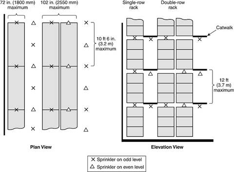
Figure 26.6.6.4 has been updated and now gives an elevation view plus a plan view. In the past version it only showed the plan view.
26.6.6.4.1 Single-Row Racks
26.6.6.4.1.2
- 2022: “sprinklers…shall be staggered horizontally such that the sprinkler at first level is not less than 18 in. (450 mm) but not greater than 24 in. (600 mm) from the face of the rack on the catwalk side.”
- “At the next level, the sprinkler in the transverse flue shall be located not less than 6 in. (150 mm) but not greater than 12 in. (300 mm) from the back face of the rack.”
- “This staggering shall be repeated throughout all catwalk levels.”
- 2025: “sprinklers…shall be installed not less than 18 in. (450 mm) but not greater than 24 in. (600 mm) from the face of the rack on the catwalk side.” — Sub-items (A) and (B) deleted; the back-face positioning rule and the explicit staggering repetition requirement are removed. Only the catwalk-side dimension is retained.”
26.6.6.4.2 Double- and Multiple-Row Racks.
- 26.6.6.4.2.2 (New in 2025): “Where only one catwalk level has been installed, both the ‘X’ and ‘Δ’ in-rack sprinklers as shown in Figure 26.6.6.4 shall be installed.”
Chapter 27 – Special Occupancy Requirements
- The term “ignitible” is used in Chapter 27 to refer to flammable or combustible materials.
27.2 Ignitible (Flammable and Combustible) Liquids.
- Title change of 27.2.
- 2022: 27.2 Flammable and Combustible Liquids.
- 2025: 27.2 Ignitible (Flammable and Combustible) Liquids.
27.6 Dipping, Coating, and Printing Processes Using Ignitible (Flammable or Combustible) Liquids.
- 2025: Fire sprinkler systems for the protection of dipping, coating, and printing processes using ignitible (flammable or combustible) liquids shall be designed and installed in accordance with this standard and NFPA 34.
Chapter 28 – Plans and Calculations
28.1 Working Plans
28.1.3
- New item (4):
- “Full height cross section or schematic diagram, including structural member information as required for clarity.”
- This shifts all subsequent items by one number (2022’s items 4–23 become 2025’s items 5–24).
- New water source subitems (m) and (n) in 2025 item (14):
- 2022: item (13) for water source information had subitems (a) through (l).
- 2025: item (14) adds:
- (m) “Size of city main in street and whether dead end or circulating; if dead end, direction and distance to nearest circulating main; and city main test results and system elevation relative to test hydrant.”
- (n) “Private fire service main sizes, lengths, locations, weights, materials, point of connection to city main; the sizes, types, and locations of valves, valve indicators, regulators, meters, and valve pits; and the depth that the top of the pipe is laid below grade.”
- New sprinkler legend item (xi) in 2025 item (18)(b): “Sprinkler wrench model number(s).” Not required in 2022.
- New maintenance information subitem iii in 2025 item (24)(d): “Location of all low point drains”
28.2 Hydraulic Calculation Procedures
28.2.4.2.3.1 (New in 2025):
- 2025: “Where additional sprinklers are carried over to the next branch line, the flow from the sprinklers that create the hydraulically most demanding remote area within the dimension required by 28.2.4.2.1 shall be selected.”
- Annex: “For most tree and loop systems, the hydraulically most demanding sprinklers will be those closest to the cross main. For gridded systems, the hydraulically most remote sprinklers could end up being any of those along the adjacent branch line, grouped together within the 1.2 length.”
28.2.4.3 CMSA Sprinkler Method
- 28.2.4.3.1
- 2022: “For CMSA sprinklers, the design area shall be a rectangular area having a dimension parallel to the branch lines at least 1.2 times the square root of the area protected by the number of sprinklers to be included in the design area. The design area protected by the number of sprinklers to be used by the 1.2 rule shall be based on the maximum allowable area per sprinkler.”
- 2025: “For CMSA sprinklers, the design area shall be a rectangular area having a dimension parallel to the branch lines determined in accordance with 28.2.4.2 with the design area (A) being calculated by multiplying the required number of sprinklers by the actual floor area covered by those sprinklers.”
- 28.2.4.3.3
- 2022: “In systems having branch lines with an insufficient number of sprinklers to fulfill the 1.2 requirement, the design area shall be extended to include sprinklers on adjacent branch lines supplied by the same cross main.”
- 2025: “In systems having branch lines with an insufficient number of sprinklers to fulfill the dimension along the branch line requirement, the design area shall be extended to include sprinklers on adjacent branch lines supplied by the same cross main.”
28.2.4.4 ESFR Sprinkler Method
- 2022: “For ESFR sprinklers, the design area shall consist of the most hydraulically demanding area of 12 sprinklers, consisting of 4 sprinklers on each of three branch lines, unless other specific numbers of design sprinklers are required in other sections of this standard.”
- 2025: “For ESFR sprinklers, the design area shall be in accordance with the applicable sections in Chapters 23 and 25.”
28.2.4.4.1 (New in 2025):
- 2025: “Where the design area was increased to 18 sprinklers due to the slope of the ceiling or roof, the design area shall be five sprinklers on the most demanding three branch lines and the three most demanding sprinklers on the next most demanding branch line.”
28.2.4.7.3 and 28.2.4.7.4 – Obstruction Sprinklers Reorganized
- 28.2.4.7.4.1 (2022 Origin 28.2.4.7.3.1):
- 2022: Sprinklers under the obstruction shall not be required to be included in the hydraulic calculation of the ceiling sprinklers.
- 2025: Suplemental sprinklers under the…
- 28.2.4.7.4.2 (Renumbered 2022 28.2.4.7.3.2)
28.2.4.7.4.3 (New in 2025) with subitems (A) through (E):
2025 adds an entirely new subsection: “Where the requirements of 28.2.4.7.4.2 are not met, a level of supplemental sprinklers shall be calculated to verify pipe sizes.”
- Maximum of four adjacent sprinklers on a branch line.
- If there is a single line of sprinklers installed under the obstruction, then four sprinklers on the same branch line should be included in the hydraulic calculations. If, however, there is more than one line of sprinklers installed under the obstruction, then the hydraulic calculations should account for two sprinklers on two lines.
- For density/area: area of coverage = footprint of obstruction only.
- For density/area: design criteria per Section 19.5.
- For CMSA and ESFR: discharge pressure per 20.16.4.
- Supplemental sprinkler level not required to be balanced with overhead system.
28.2.4.8.1
- Item (1) expanded to include flexible hose fittings:
- 2022: “Pipe, fittings, and devices such as valves, meters, flow switches in pipes 2 in. (50 mm) or less in size, and strainers shall be included…”
- 2025: “Pipe, fittings, flexible sprinkler hose fittings, and devices such as valves, meters, flow switches, and strainers shall be included…” — Adds flexible hose fittings explicitly; removes the 2 in. size qualifier from flow switches.
- Added item (12) – Flexible hose fitting losses:
- 2025 inserts: “(12) Losses for flexible sprinkler hose fittings shall be based upon the number of bends referenced in the listing for the hose length.”
- Added item (15) – Vacuum pressure C value = 120:
- 2025: “(15) In new systems, an increased C value of 120 shall be permitted where vacuum pressure is provided in accordance with Section 8.11.”
- Added item (16) – Vapor corrosion inhibitor C value = 120:
- 2025: “(16) In new systems, an increased C value of 120 shall be permitted where a vapor corrosion inhibitor is provided in accordance with 8.2.11.”
28.2.4.12 Maximum Operating Pressure
- 2022: “For extra hazard occupancies, palletized, solid-piled, bin box, back-to-back shelf storage, shelf storage, or rack storage, the maximum operating pressure of any sprinkler shall be 175 psi (12 bar).”
- 2025: “For sprinklers in extra hazard occupancies or designed in accordance with Chapters 20 through 26, the maximum operating pressure of any sprinkler shall be 175 psi (12 bar).”
28.4 Hydraulic Calculation Forms and Reports
Section title updated:
- 2022: “28.4 Hydraulic Calculation Forms”
- 2025: “28.4 Hydraulic Calculation Forms and Reports”
Subsection titles changed:
28.4.1 Handwritten Hydraulic Calculation Forms (2022 – 28.4.1 General)
28.5 Pipe Schedules
28.5.1 General
28.5.1.2 Pipe Schedule Exclusions (substantive)
- 2022: Single sentence: “Sprinkler systems having sprinklers with K-factors other than 5.6 nominal, listed piping material other than that covered in Table 7.3.1.1, extra hazard Group 1 and Group 2 systems, and exposure protection systems shall be hydraulically calculated.”
- 2025: Converted to numbered list with added item: “(3) Those having listed fittings other than what is covered in Table 7.4.1”.
Chapter 29 – Systems Acceptance
29.1 Approval of Sprinkler Systems
Title change
- 2022: referenced “Sprinkler Systems and Private Fire Service Mains.”
- 2025: title is just “Approval of Sprinkler Systems.”
29.1.2 (New in 2025):
- 2025: “The approval of sprinkler systems shall be permitted to be witnessed remotely in accordance with NFPA 915.”
29.1.3 (New in 2025):
- 2025: “The requirements of 29.2.7 shall apply when acceptance tests are automated.”
29.2 Acceptance Requirements
29.2.1 Hydrostatic Tests
29.2.1.4 Fire Pump Test Pressure
- 2022: “Where a fire pump is used for a system, the test pressure shall be determined using the shutoff pressure of the pump.”
- 2025: “…the test pressure shall be determined using the shutoff pressure of the pump plus the maximum static pressure of the water supply adjusted for elevation.”
- 29.2.1.4.1:
- 2022: “Where a fire pump uses a pressure limiting device or variable speed motor, the test pressure shall be calculated ignoring the settings of the pressure limiting device.”
- 2025′: “Where a fire pump uses a pressure limiting device or variable speed motor, the test pressure shall be based on the set pressure of the main relief valve.”
- 29.2.1.4.2 (New in 2025): “Where a main relief valve is not provided, the pressure shall be calculated ignoring the settings of the pressure limiting device.” — This preserves the 2022 rule as a fallback when no main relief valve exists, while establishing the relief valve set pressure as the primary basis.
29.2.1.8 Fire Department Connection Piping
- 2022: “…Piping between the exterior fire department connection and the check valve in the fire department inlet pipe shall be hydrostatically tested in the same manner as the balance of the system. After repair or replacement work affecting the fire department connection, the piping between the exterior and the check valve in the fire department inlet pipe shall be isolated and hydrostatically tested at 150 psi (10 bar).”
- 2025: Only the first sentence retained: “Piping between the fire department connection and the check valve in the fire department inlet pipe shall be hydrostatically tested in the same manner as the balance of the system.”
29.2.1.13 Differential Valve Clapper:
- 2022: “When subject to hydrostatic test pressures, the clapper of a differential-type valve shall be held off its seat to prevent damaging the valve.”
- 2025: “…the clapper of a dry pipe valve shall be in the position as stated by the manufacturer’s published instructions to prevent damaging the valve.”
29.2.3.2 Dry Pipe and Double Interlock Preaction Systems.
29.2.3.2.4 Dry System Air Pressurization (New in 2025, Former 29.2.3.2.4 Deleted)
- 2022: “The results shall be recorded using the contractor’s material and test certificate for aboveground piping… and the general information sign…”
- 2025: “Systems shall be filled with air through the approved air supply until the required set pressure of the valve is met.” and inserts two completely new subsections:
29.2.3.2.4.1 (New in 2025):
- “The system shall reach the required set pressure within 30 minutes from the time the air supply is opened.”
29.2.3.2.4.2 (New in 2025):
- “Systems maintained at or below 5°F (-15°C) shall be permitted to reach the required set pressure within 60 minutes.”
29.2.3.6 Wet Pipe System Air Venting Valves (New in 2025)
- 2025 adds an entirely new operational test subsection:
- 29.2.3.6.1: “Where manual valves are installed in accordance with Section 16.7 to meet the air venting requirements of 8.1.5, they shall be operated during filling of the system.”
- 29.2.3.6.2: “Manual valves shall remain open until water reaches the valve and trapped air has escaped.”
29.2.8 Negative Pressure Systems (New in 2025)
- 2025 adds a new section:
- 29.2.8.1: “Vacuum dry pipe systems shall meet all of the acceptance testing requirements for dry pipe systems.”
- 29.2.8.2: “Vacuum preaction systems shall meet the acceptance testing requirements for preaction systems.”
29.6 General Information Sign
29.6.1.2 Sign Placement
- 2022: “Such signs shall be placed at each system control riser, antifreeze loop, and auxiliary system control valve.”
- 2025: “Such signs shall be placed at each system riser.” The specific requirements for antifreeze loops and auxiliary system control valves are removed, leaving only “system riser.”
29.6.2 General Information Sign Contents
- 2025 inserts item (2): “Edition of NFPA 13.”
Chapter 30 – Existing System Modifications
Title Change:
- 2022: “Existing System Modifications”
- 2025: “Existing System Modifications or Evaluation”
30.1 General
30.1.1
- 2022: “In addition to the applicable requirements of this standard, the requirements of Chapter 29 shall apply where modifications or additions are made to existing systems.”
- 2025: “…where modifications, evaluations, or additions are made to existing systems.”
30.1.4
- 2025 Added Annex 30.1.4: “It is not the intent of this section to require a full hydraulic analysis of the existing piping system. This requirement should only verify that the additional friction loss through the backflow prevention device is not detrimental to the original calculations when compared with the new flow test data.”
30.1.5 (New in 2025):
- “Where existing system modifications include added or relocated sprinklers, or flexible sprinkler hose fittings are retroactively installed on existing systems, a hydraulic analysis or revised hydraulic calculations using current water supply data to accommodate the additional friction loss shall be completed as a part of the installation.”
30.3 Sprinklers
30.3.8 (New in 2025):
- “Sprinklers having a K-factor exceeding K-5.6 (80) and having ½ in. (15 mm) National Pipe Thread (NPT) shall be permitted to be installed in existing sprinkler systems if listed for such use.”
30.4 Evaluation of Existing Systems. (AUT-SSD) (New in 2025)
Added Annex A30.4:
- “Fire protection systems are designed and installed based on a specific set of circumstances and building uses. For example, the volume of water needed for a sprinkler system to control a fire in the built environment is based upon the intended use of the facility known at the time the sprinkler system was designed and installed. Revisions to properties used for storage represent one of the most common scenarios that impact the ability of systems to provide adequate protection. Some of the most common changes include raising the storage height, changing the storage method arrangement such as adding racks, installing solid shelves in rack structures, or decreasing the aisle widths between racks. Changes in product packaging with the use of foam inserts, bubble wrap, or other plastics or encapsulated storage can significantly increase the fire hazard. Changing from wood pallets to plastic pallets, converting to the use of plastic bin boxes, or revising or adding material handling systems such as conveyors could severely impact the effectiveness of the fire protection systems. The following are some examples of when existing system evaluations should be conducted:
- Tenant changes or process changes
- Occupancy or storage changes
- Fire pump replacements
- Water supply changes
- Backflow preventers replaced or added
- Replacing missing hydraulic information signs with no existing records”
30.4.1 General (New in 2025):
- “Where changes in the occupancy, hazard, water supply, storage commodity, storage arrangement, building modification, or other condition that affects the installation criteria of the system are identified, the existing system shall be evaluated based on the current hazard and water supply.”
30.4.2 Evaluation (New in 2025):
- “Evaluation of existing systems shall be in accordance with one of the following methods:
- As a new system in accordance with this edition of the standard
- In accordance with the edition of NFPA 13 utilized in the design and installation of the system”
- Annex: “Evaluation of existing systems is in references to the adequacy of the pipe schedule hazard classification and design densities (in the case of CMDA systems), as well as the number of sprinklers and pressures calculated with ESFR and CMSA sprinklers or systems. The evaluation of existing systems is not limited to storage applications but encompasses all occupancies. This section provides users with two options for evaluation of existing systems. The first option would be to treat the system as new by applying and using the nonexisting requirements in the current edition. The second option is to apply the edition of NFPA 13 that the sprinkler system was originally designed under.”
30.5 Modification of Existing Systems:
- 2022: “30.5 Existing Systems Area/Density Curves” (single paragraph)
- A single-paragraph pointing to existing system density/area curves in Chapters 19, 21, and 25 is removed.
- 2025: “30.5 Modification of Existing Systems” (new multi-subsection section)
- 2025 Section 30.5 consolidates pipe schedule and hydraulic revamping content formerly in 30.4 and 30.6:
30.5.1 Revamping of Pipe Schedule Systems (New in 2025):
Table 30.5.1.1 Extra Hazard Pipe Schedule (New in 2025)
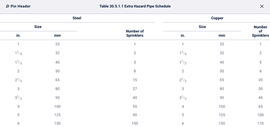
30.5.2 Revamping of Hydraulic Design Systems (2022 Origin 30.6.1 – 30.6.4).
30.5.2.2 Annex (New in 2025):
- “It is not the intent of this section to require a full hydraulic analysis of the existing piping system in addition to the new sprinkler layout.”
30.6 System Design
30.6.5: “For modifications to existing systems equipped with ESFR sprinklers where ESFR sprinklers are used for the protection of light or ordinary hazard occupancies, 30.6.5.1 through 30.6.5.3 shall be permitted.”
- 30.6.5.1: “In light hazard occupancies, the protection area limitations of ESFR sprinklers shall be permitted to meet the protection area requirements of Table 10.2.4.2.1(a).”
- 30.6.5.2: “In light and ordinary hazard occupancies, the sprinkler spacing of ESFR sprinklers shall be permitted to meet the sprinkler spacing requirements of 10.2.5.”
- 30.6.5.3: “In light and ordinary hazard occupancies, the obstruction to the sprinkler discharge pattern of ESFR sprinklers shall be permitted to meet the obstruction discharge requirements of 10.2.7.2.”
30.7 Testing
30.7.1
- 2022: “Modifications to existing piping systems shall require testing at system working pressure.”
- 2025: “Modifications to existing piping systems shall be isolated and hydrostatically tested in accordance with 29.2.1.”
30.7.1.1:
- 2022: “Where modification is made to an existing system affecting more than 20 sprinklers, the new portion shall be isolated and tested at not less than 200 psi (14 bar) for 2 hours.”
- 2025: “Where modifications affect 20 sprinklers or less, the new portion shall be hydrostatically tested at system working pressure.”
30.7.1.2:
- 2022: “Modifications that cannot be isolated, such as relocated drops, shall require testing at system working pressure.”
- 2025: “Regardless of the number of sprinklers affected, modifications that cannot be isolated shall be hydrostatically tested at system working pressure..”
30.7.1.3:
- “Modifications to deluge systems shall be permitted to be flow tested in lieu of hydrostatic testing, to verify all the following:
- Water discharge patterns from all the open spray nozzles or sprinklers
- Adequate coverage of wetting surfaces to be protected
- Design pressure at the most remote nozzle or sprinkler
- Design pressure at the deluge valve”
Chapter 31 – Marine Systems
Identical to 2022.
Chapter 32 – System Inspection, Testing, and Maintenance
Identical to 2022.